
PT-100 Manual


© 2017 Sensata TechnologiesPage 14
Installation
12345678910
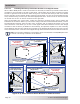
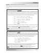
P1 P1
Top Controller
Mounting Keyholes
(see Keyhole Details)
P1
Bottom Controller
Mounting Holes
(Ø.180 Thru Hole x 2)
P2
P2
P2
0.180"
(4.6 mm)
0.350"
(8.9 mm)
Keyhole Details (x2)
To mount the charge controller to the
wall-mounting bracket:
1. Using two of the #8 Phillips head screws
provided, insert the screws into the top
two mounting holes of the wall-mounting
bracket (designated as “P1” in Figure
2-10). Tighten these screws until there is
a ¼” (6.4 mm) gap between the bracket’s
mounting hole surface and the screw head.
2. Hang the PT controller onto the wall-
mounting bracket by placing the two keyhole
openings of the PT controller (designated
as “P1” in Figure 2-11) onto the two #8
screws—ensuring the controller is securely
held in place before releasing.
3. Align the two mounting holes in the bottom
of the PT controller (designated as “P2” in
Figure 2-11) over the two bottom mounting
holes on the bracket (designated as “P2” in
Figure 2-10).
4. While holding the controller over these
bottom mounting holes, insert the other
two #8 Phillips screws provided.
5. Secure the PT controller to the mounting
surface by tightening all four of the Phillips
screws, and then verify that the controller
is fi rmly attached to the mounting bracket.
2.3.6.2.2 Mounting the Charge Controller on the Wall-mounting Bracket
Once the wall-mounting bracket is securely fastened to the vertical surface, you can now attach the
PT charge controller. Refer to Figures 2-11 and 2-12.
Figure 2-11, PT Controller
Mounting Holes