
PT-100 Manual


© 2017 Sensata TechnologiesPage 16
Installation
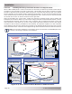
2.4 Electrical System Wiring Diagrams
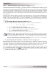
A diagram of the PV and battery wiring for the PT-100 controller is shown in Figure 2-14 and is
provided to assist you or your system installer. Due to the variety of applications and differences in
local and national electrical codes, this wiring diagram should only be used as a general guideline. It
is not intended to override or restrict any national or local electrical codes; and, this diagram should
not be the determining factor as to whether the installation is compliant, that is the responsibility
of the electrician and the onsite inspector.
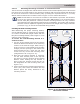
Info: The MP and MMP Series panels have been specifi cally designed to conveniently
connect a Magnum inverter and the PT-100 charge controller. The panels allow the PT-
100’s required PV and battery DC disconnects and all common wire connection points
to be connected together, accessible from the front and marked in an easy to install
pre-wired enclosure.
Figure 2-14, PT-100 Controller - System Wiring
Note 1: When PV system is not solidly grounded, disconnecting means are required in both legs of PV circuit.
Note 2: The battery negative-to-ground connection is only made inside the PT-100 controller. If another battery
negative-to-ground connection is made, then the GFDI (Ground Fault Detection/Interruption) feature must be
disabled or the GFDI fault (F12) will activate.
Note 3: Breaker provides disconnect and overcurrent protection.
BATTERY
BANK
PV ARRAY
DISCONNECT
1
Internal GFDI
2
GROUND
PV STRING
PV ARRAY
OUTPUT
GROUND
PV STRING
PV
OUTPUT
GROUND
PV STRING
PV
OUTPUT
PV STRING
COMBINER
(with breakers or
fused disconnects)
DC SHUNT
GROUND
BUS
EARTH
GROUND
INVERTER
BATTERY
BREAKER
3
ISOLATED
NEGATIVE
BUS
CONTROLLER
BATTERY
BREAKER
3
INVERTER
BATTERY
INPUT
DC
GROUND
PV SOURCE CIRCUITS
PT-100
CHARGE CONTROLLER
PV
ARRAY
INPUT
GND
BATTERY
OUTPUT