
PT-100 Manual


Page 21
© 2017 Sensata Technologies
Installation
2.5.4 Determining the Lower Maximum Power Voltage (V
MP-LOW
)
Lastly, you must ensure the maximum power voltage (V
MP
) of the individual module at the lowest
expected temperature does not fall below the controller’s lower MPPT voltage limit. When determining
the number of modules in series, the V
MP
of the modules connected in series should normally
operate within the MMPT voltage range of the PT-100; thereby, maximizing the energy output of
the PV system. This section details how to calculate the V
MP
of the individual module at the lowest
expected temperature, and how to use this value to determine the minimum number of modules
allowed to be connected in series that will stay above the lower MMPT voltage limit of the PT-100.
• 3A) Calculating Module’s Lower V
MP
Level
Because PV modules have a reduction in voltage at high temperatures, make sure the V
MP
of the
modules connected in series do not fall below the controller’s lower MPPT voltage limit. Otherwise,
the PT-100 will adjust to its lower MPPT voltage limit—resulting in power loss. To do this, the V
MP
of the individual module at the lowest expected temperature (at the installation location) must
fi rst be determined.
Info: The module’s lower V
MP
level (V
MP-LOW
) is directly dependant on the module’s highest
temperature and the particular method used to mount the PV array.
To calculate the module’s lower V
MP
(V
MP-LOW
) level, use the formula below:
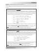
V
MP-LOW
= ⟨V
MP
× [(T
AVG-H
+ T
Rise
− T
STC
) × αV
MP
(V)]⟩ x 0.80
1
• V
MP-LOW
= module’s lower V
MP
level
• V
MP
= module’s voltage at maximum power output
• T
AVG-H
= module’s temperature at the highest average temperature
2
• T
Rise
= temperature rise applied based on PV module’s mounting method
a) Parallel to roof (<6” inches of clearance behind them): +35°C
b) Rack-type mount (>6” inches of clearance behind them): +30°C
c) Pole mount or free standing (plenty of air circulation around them):+25°C
• T
STC
= module’s temperature at STC (25°C)
• αV
MP
(V) = temperature coeffi cient of V
MP
provided as voltage
Info: Different PV mounting methods cause the module temperature to rise and the
modules to operate at lower maximum power point voltage levels. There are three
typical PV array mounting methods: 1) Parallel to Roof - the modules are fl at against
the roof, have less than 6” inches of clearance behind them, or have no air circulation
on the back side, and have about a 35°C temperature rise. 2) Rack-type mount - the
modules have at least 6” behind the panel and the roof, or are mounted at an angle so
air can circulate behind, and have about a 30°C temperature rise. 3) Pole mount or a
freestanding frame - the modules are above the ground with plenty of air circulation,
and have a temperature rise of about 25°C.
Info: If the V
MP
temperature coeffi cient is listed as percentage instead of voltage, you can
convert %/°C to V/°C by multiplying the V
MP
by the percentage temperature coeffi cient.
For example: If the V
MP
is 29.5V and the V
MP
temperature coeffi cient is -0.45%/°C, then
the V temp coeffi cient is: 29.5V x -0.45%/°C = -0.133V/°C.
Note 1: 0.80 derating multiplier. A derating multiplier that takes into consideration several factors for low
voltage issues is applied. Derating factors include the voltage drop of the cables from the PV array to the
controller, operating at low irradiance levels less than STC (1kW/m²), and degradation and high voltage
tolerances of the module. Taking all these factors into account, a 20% derating multiplier (0.80) is applied.
Note 2: When determining the highest average temperature value for your location, many resources can be
used. You can use the Average High Temperature (highest month) at www.weatherbase.com and at www.
weather.com. Additionally, you can use the 2% Annual Design Dry Bulb Temperature
found in the ASHRAE
Handbook – Fundamentals, which can be found using the interactive Solar Reference Map at: www.solarabcs.
org/permitting/map, shown on the map as High Temp. (2% Avg.).