
PT-100 Manual


Page 23
© 2017 Sensata Technologies
Installation
2.6 Conductor Sizing for the PV System
It is important to use the correct sized DC wire (or conductor) in a Standalone PV System (includes
PV, controller and standalone inverter) to achieve maximum system effi ciency and to reduce fi re
hazards associated with overheating. The NEC (Section 690) provides the requirements for proper
conductor sizing and current calculations for PV systems. This section will help you to correctly
size the conductors in your PV system by following a set of calculations in sequence.
You must determine the maximum current for each PV circuit, then select a conductor that will
handle this maximum current (under all conditions), and fi nally, select an overcurrent protection
device that correctly protects the conductor.
2.6.1 Determining Maximum Circuit Currents (I
MAX
)
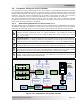
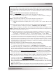
The NEC defi nes how to calculate the maximum circuit current values in a Standalone PV System.
To calculate and apply the maximum current values, determine the specifi c circuit you are dealing
with from the list below. Figure 2-15 is provided to help illustrate the specifi c current circuits.
1
PV Source Circuits - conductors between modules and from the modules to the DC
system’s common connection point (i.e., String Combiner). The maximum current for
each series-string source circuit is the module’s rated short circuit current (I
SC
) x 125%
(I
MAX
= I
SC
x 1.25).
2
PV Output Circuit - conductors between the photovoltaic source circuit(s) and the DC uti-
lization equipment (i.e., Charge Controller). The maximum current for this circuit is the sum
of the PV source circuit maximum currents in parallel (I
MAX
= I
SC
x 1.25 x parallel strings).
3
PT-100 Output Circuit - conductors between the PT-100 and the battery. The maximum
current for this circuit is the controller’s maximum output current rating (I
MAX
= 100ADC).
4
Standalone Inverter DC Input Circuit - conductors between the inverter and the battery.
The maximum current for this circuit is the standalone continuous inverter input current
rating when the inverter is producing rated power at the lowest input voltage.
5
Inverter AC Output Circuit - conductors that run from the AC output terminals of the
inverter to the inverter’s AC electrical panel. The maximum current for this circuit is the
inverter’s continuous output current rating.
Fused
PV String
Combiner
AC Loads
Panel
Standalone
Inverter/
Charger
PV
Source
Circuits
Inverter
AC Output
Circuit
Inverter
DC Input
Circuit
1
45
PV String 1
PV String 2
PV String 3
PV
Disconnect
Battery
Breaker
PV
Output
Circuit
2
PT-100
MPPT
Charge
Controller
Battery
Bank
123456789
PT-100
Output
Circuit
3
Battery
Breaker
Figure 2-15, Standalone PV System Circuits