
PT-100 Manual


Page 27
© 2017 Sensata Technologies
Installation
2.6.4 Steps to Sizing Conductors and Overcurrent Protection in a PV System
Info: A worksheet to help size PV conductors and overcurrent protection devices using
the following steps is provided in Appendix D.
Info: Tables referenced in this section are from the 2014 Edition of the National Electrical
Code® (also known as NFPA 70).
To calculate the required conductor and the overcurrent protection device size, follow these steps:
Step 1 - Calculate the maximum current for the circuits (I
MAX
).
Step 2 - Determine the conductor size for the continuous circuit currents (I
CONT
).
a) Calculate the continuous current for the circuit (I
CONT
).
b) Find the conductor sized for continuous current.
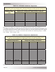
Look at Table 310.15(B)(16) and select the temperature rating column that corresponds to the
lowest temperature rating of any terminal the conductor is terminated on, regardless of the
insulation of the selected conductor. Select the smallest conductor that exceeds the continuous
current (I
CONT
) calculation from Step 2a.
Step 3 - Determine the conductor size for the maximum circuit currents derated after adjustment
factors (I
DERATE
).
a) Calculate the ampacity of the conductors after derating by the following “conditions of use” factors:
1. Conduit Fill Factor (Fill Factor) – When more than three current carrying conductors are in conduit (or
bundled together) in continuous lengths >24 inches, divide by the Conduit Fill Factor from Table 310.15(B)
(3)(a).
2. Temperature Correction Factor (Temp Factor) - If the average ambient temperature (Avg. Temp)—in
addition to the Rooftop Temperature Adder*—is greater than 30°C, then these two temperatures become the
effective ambient temperature (Eff. Temp) value. Use this effective temperature to determine the appropriate
Correction Factor** from Table 310.15(B)(2)(a).
* Rooftop Temperature Adder (Rooftop Add.) – Conductors/raceways exposed to sunlight on a roof require
the ambient temperature to be increased—based on the distance from the roof—using a Temperature Adder
from Table 310.15(B)(3)(c).
**Correction Factor – To determine the correct temperature factor, the conductor’s temperature rating is
required.
b) Find the conductor sized after derating factors have been applied:
Look at Table 310.15(B)(16) and select the temperature rating column that corresponds to the
lowest temperature rating of any terminal the conductor is terminated on, regardless of the
insulation of the selected conductor. Select the smallest conductor that exceeds the derated
current (I
DERATE
) calculation from Step 3a.
Step 4 - Determine the minimum required conductor size.
Compare the conductor sized to the continuous current (Step 2b) against the conductor sized
after derating factors (Step 3b); the largest conductor between the two is the minimum required
conductor size.
Step 5 - Size the Overcurrent Protection Device (OCPD) to protect the selected conductor.
Ensure the size of the OCPD is equal to or greater than the Continuous Current (see Step 2)
and less than or equal to the ampacity of the Minimum Required Conductor (see Step 4) using a
commonly available size (see NEC Article 240.6).
Notes:
1. If the OCPD is rated for 100% operation, then it can be sized to the lower I
MAX
current (Step 1).
2. The OCPD for each PV source conductor cannot exceed the “Series fuse” listed on the module label.
3. Consult the manufacturer for OCPD rating if exposed to temperatures greater than 40°C.