
PT-100 Manual


© 2017 Sensata TechnologiesPage 32
Installation
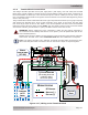
2.7 Wiring the PT-100
This section describes the requirements and recommendations for wiring the PT charge controller.
The NEC (National Electric Code, ANSI/NFPA 70) for the United States and the CEC (Canadian Electrical
Code) for Canada provide the standards for safely wiring residential and commercial installations.
WARNING: Wiring to the PT charge controller should meet all local codes and standards
and be performed by qualifi ed personnel such as a licensed electrician.
WARNING: Ensure all power (i.e., batteries, solar) is de-energized (i.e., breakers
opened, fuses removed) before proceeding—to prevent accidental shock.
CAUTION: The PT controller is NOT reverse polarity protected—which means that if the
negative and positive voltage (from either the PV or battery) is connected backwards to
the charge controller, the charge controller will likely be damaged. You should verify the
correct voltage polarity using a voltmeter BEFORE connecting any wires.
2.7.1 Wiring Requirements
• All PV and battery conductors that are at risk for physical damage must be protected by
conduit, tape, or placed in a raceway; and any knockout opening on the controller wiring box
must be protected with conduit or with a bushing.
• Always check for existing electrical, plumbing, or other areas of potential damage prior to
making cuts in structural surfaces or walls.
• To prevent electrical interference, do not mix power wires (i.e., PV and/or battery) in the same
conduit or panel with signal/communications wires.
• The PT controller disconnects the PV input from the battery during night time or low sunlight
conditions; this means blocking diodes are not required to prevent reverse current leakage.
• DC overcurrent protection for the PV and battery wires must be provided as part of the installation.
• The negative-to-ground connection is provided in the charge controller. Negative should not be
bonded to ground anywhere else in the system to ensure the GFDI circuit operates correctly.
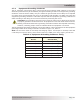
• Use only copper wires with a minimum temperature rating of 75°C. The wire sizes recommended
are based on the ampacities given in Table 310.16 (in conduit) of the NEC, ANSI/NFPA 70, for
75°C (167°F) copper wire and based on an ambient temperature of 30°C (86°F).
• The NEC requires DC overcurrent protection for the PV and battery wires; and that the DC circuit
conductors and overcurrent devices from the photovoltaic system to the charge controller and
from the charge controller to the battery bank be sized to carry not less than 125% of the
circuit’s maximum output current rating.
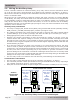
• To ensure the maximum performance from the controller, all connections from the battery
bank to the controller should be minimized. The exception is the DC overcurrent disconnect
in the positive line and a shunt in the negative line. Any other additional connections will
contribute to additional voltage drops and may loosen during use.
• All wiring to the terminals should be checked periodically (~every 6 months) for proper tightness.
If you don’t have a torque wrench, ensure all DC terminals are tight and cannot move.
• Color code the DC wires with colored tape or heat shrink tubing: RED for positive (+); WHITE
for negative (-); and GREEN (or bare copper) for DC ground, to avoid polarity problems.
• PV module interconnections should be 90ºC wet-rated conductors. Allowable wire types are:
• USE-2 single conductor cable for exposed applications
• Type TC multi-conductor cable for exposed applications with THWN-2 or XHHW-2 or
RHW-2 or equivalent 90ºC wet-rated conductors in the cable.
• Type THWN-2 or XHHW-2 or RHW-2 or equivalent 90ºC wet-rated conductors in high
temperature conduit (conduit rated for a minimum of 75ºC wet conditions).
• All wiring should be sized to minimize voltage drop.
• Ensure all wires and conduit are correctly secured/supported.
• The insulation of the wires (both power and communication) must be rated to handle the
highest voltage within the wiring access area.