
PT-100 Manual


Page 33
© 2017 Sensata Technologies
Installation
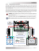
2.7.2 Wire Routing
Before connecting any wires, determine all wire routes to and from the charge controller, such as:
• PV input wiring from the PV array/combiner to the charge controller
• Battery output wiring from the charge controller to the batteries
• Battery Temperature Sensor cable from the charge controller to the batteries
• Network cable from the charge controller to the inverter (optional)
• Ground wiring to and from the charge controller
• Auxiliary relay wiring to and from the controller wiring compartment
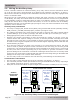
• If stacking, determine how to run power and communication cables from one controller to
another controller
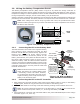
2.7.3 Torque Requirements
Follow the specifi c torque recommendations below to ensure your fasteners are tightened suffi ciently.
To ensure your connections are correct, you should use an accurate, quality torque screwdriver/
wrench. It is highly recommended to go back over all fasteners and re-torque 5 days after the initial
installation—and every 6 months thereafter.
CAUTION: DC power/wire connections that are under-torqued could become loose
and result in a fi re hazard. On the other hand, over-tightening a screw/bolt could
cause the fastener to be snapped off.
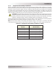
Table 2-6, Torque Values for the DC Terminal Block
Wire Size #2 Phillips Screw Torque Value
#20 to 1 AWG
(0.5 to 42.4 mm
2
)
30 in lbf
(3.4 N-m)
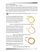
Table 2-7, Torque Values for the Ground Busbar
(this busbar has different torque values for the small and large screws)
Wire Size
Busbar Screw Size Torque Values
10-32 (Small Screw) 5/16-24 (Large Screw)
#14 to 10 AWG
(2.08 to 5.26 mm
2
)
15 in. lbs.
(1.7 N-m)
35 in. lbs.
(4.0 N-m)
8 AWG
(8.36 mm
2
)
20 in. lbs.
(2.3 N-m)
40 in. lbs.
(4.5 N-m)
6 AWG
(13.3 mm
2
)
25 in. lbs.
(2.8 N-m)
45 in. lbs.
(5.1 N-m)
4 AWG
(21.1 mm
2
)
NA
45 in. lbs.
(5.1 N-m)
#3 to 1/0 AWG
(26.7 to 53.5 mm
2
)
NA
50 in. lbs.
(5.6 N-m)