
PT-100 Manual


© 2017 Sensata TechnologiesPage 34
Installation
2.7.4 PT-100 Output Conductor Size
It is important to use the correct sized DC wire to achieve maximum effi ciency from the system and
to reduce fi re hazards associated with overheating. Always keep your wire runs as short as practical.
For correctly sizing the PV source and PV output conductors (and corresponding overcurrent device)
see Section 2.6. For the PT-100 output, use the conductor size listed in Table 2-8, which is based
on the PT-100’s maximum output current rating (I
MAX
= 100 amps).
If the distance from the charge controller to the battery bank is >5 feet, the DC wire will need
to be increased. Longer distances cause an increase in resistance, which affects the charging
performance to the battery. Use the conductor size listed in the lower part of Table 2-8 to determine
the minimum DC wire size needed for various distances.
2.7.5 Overcurrent Protection for the PT-100 Output Conductor
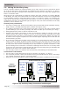
In a residential or commercial electrical installation, the NEC requires both overcurrent protection
and a disconnect switch for all circuits in the PV system. A DC overcurrent protection device
(OCPD) must be installed in the positive DC conductor side
1
, it can be a fuse or a circuit breaker,
and must have the appropriate DC voltage, current, and interrupt ratings. It must be correctly
sized according to the size of the DC conductor being used, which means it is required to open
before the conductor reaches its maximum current carrying capability, thereby preventing a fi re. If
a circuit breaker is used as the overcurrent protection device, it can also be used as the required
DC disconnect. Since the PT-100 is energized from more than one source (PV and battery), a
separate PV and battery disconnect is required. The disconnects in the system must be able to
be manually operable without exposing the operator to contact with live parts, grouped together
and identifi ed, be readily accessible, and plainly indicate whether they are in the ON (closed) or
OFF (open) position.
For information on correctly sizing the OCPD for the PV source and PV output conductors, see
Section 2.6. For the PT-100 output, use the DC overcurrent device in Table 2-8, which is used to
protect the recommended minimum wire size for the PT-100 charge controller.
Info: The MP and MMP Series panels which have been specifi cally designed to
conveniently connect a Magnum inverter and the PT-100 charge controller together.
These panels allow the PT-100’s required PV and battery DC disconnects and all wire
connection points to be connected together, accessible from the front, and marked in an
easy to install pre-wired enclosure.
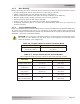
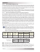
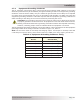
Table 2-8, Recommended DC Wire/Overcurrent Device for PT-100
Charge
Controller
Model
Maximum
Continuous
Output
Current
Recommended
OCPD
(DC Breaker)
Size
2
Using Conduit In Free Air
DC
Grounding
Electrode
Wire Size
4
Minimum DC
Wire Size
3
[rating]
Minimum DC
Wire Size
3
[rating]
PT-100 100 amps 125 amps
1 AWG
(42.4mm²)
[130 amps]
4 AWG
(21.1mm²)
[125 amps]
6 AWG
(13.3mm²)
▼▼
Increased size for
longer distance
5 to 10 feet =
1 AWG
(42.4mm²)
2 AWG
(33.6mm²)
10 to 15 feet =
1/0 AWG
(53.5mm²)
1 AWG
(42.4mm²)
Note
1
– The PT-100 can only be installed in a negative-grounded system.
Note
2
– If the OCPD is rated for 100% continuous operation, then it can be sized to 100 amps.
Note
3
– Copper wire rated with 75°C (167°F) insulation at an ambient temperature of 30°C (86°F). If us-
ing conduit, temperature and cable fi ll derating maybe required—they were not applied in this calculation.
Note
4
– Per the NEC, the DC grounding electrode conductor can be a 6 AWG conductor if that is the only
connection to the grounding electrode and that grounding electrode is a rod, pipe, or plate electrode.