
PT-100 Manual


Page 35
© 2017 Sensata Technologies
Installation
2.7.6 Equipment Grounding Conductor
The PT controller case and all other noncurrent-carrying exposed metal surfaces in the entire
electrical system that may be accidentally energized must be grounded. The equipment-grounding
conductor must be sized to safely carry the maximum ground-fault current likely to be imposed
on it from where a ground-fault may occur. In accordance with the NEC, use Table 2-9 to size the
equipment-grounding conductors. This table requires that the equipment-grounding conductor be
sized according to the rating of the overcurrent device protecting the circuit.
CAUTION: The grounding conductor wiring must be continuous to allow fault currents
to properly operate overcurrent devices. If equipment is removed which disconnects the
bonding connection between the grounding electrode conductor and exposed conducting
surfaces, a bonding jumper must be installed while the equipment is removed.
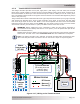
The DC equipment grounding conductor is sized per Table 2-9 and connected to the DC equipment
grounding busbar on the charge controller as shown in Figure 1-2, Item 11.
Note: The PT-100 is rated for 100 amps full charging output. This output is normally sized with
a 125-amp overcurrent device, which would require a 6 AWG (13.3 mm
2
) copper ground wire.
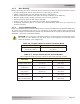
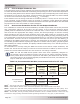
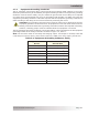
Table 2-9, Equipment Grounding Conductor Sizing
Rating of Overcurrent
Device
Minimum Size of Copper
Ground Wire
15 amps 14 AWG (2.1 mm
2
)
20 amps 12 AWG (3.3 mm
2
)
30 to 60 amps 10 AWG (5.3 mm
2
)
100 amps 8 AWG (8.4 mm
2
)
200 amps 6 AWG (13.3 mm
2
)
300 amps 4 AWG (21.1 mm
2
)
400 amps 3 AWG (26.7 mm
2
)