
PT-100 Manual


Page 37
© 2017 Sensata Technologies
Installation
2.7.8 Terminal Block Connections
The charge controller provides a four-pole, high power (125 amps), 600-volt rated, DC terminal
block and a ground busbar to connect the PV input and battery output wires. Each connection on
the terminal block is rated up to 75°C and can accept one #20 to 1 AWG (0.5 to 42.4 mm
2
) wire.
Use a #2 Phillips head screwdriver to tighten each connection to a recommended tightening torque
of 30 in lbf (3.4 N-m).
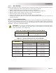
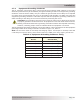
The ground busbar uses fi ve slotted head screw-type compression terminals (no ring lugs required)
and accepts CU stranded wire. Three of the terminals use a small 10-32 screw, and the other
two use a larger 5/16-24 screw. See Table 2-7 for the acceptable wire sizes and recommended
tightening torque values for these screws. Note: Two Torx head screws on each end of the busbar
are used to hold the ground busbar in place, DO NOT remove these two screws.
WARNING: Before making any wire connections, make sure the charge controller is
not connected to the battery and there is no PV power (cover all panels and open all PV
source breakers/fuses).
DO NOT close the PV or battery circuit breaker to connect power to the charge controller
at this time. This will occur in the Functional Test after the installation is complete.
Info: The charge controller’s PV- and BAT- terminals are electrically connected to each
other internally and either connection can be used for the input or output negative.
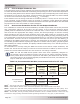
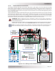
Figure 2-17, Wiring to DC Terminal Block
BATTERY
BANK
WIRING
COMPARTMENT
(PT-100)
TO SYSTEM GROUND
[Grounding Electrode
Conductor (GEC)
connection point]
BAT+ BREAKER
PV DISCONNECT
WIRING LEGEND
N
EGATIVE (-)
P
OSITIVE (+)
DC G
ROUND
BTS
BATTERY ENCLOSURE
PV
C
OMBINER
OR
PV
A
RRAY
23456789
1