
PT-100 Manual


Page 39
© 2017 Sensata Technologies
Installation
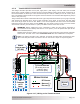
2.8 Wiring the Battery Temperature Sensor
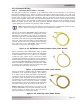
The Battery Temperature Sensor (BTS) shown in Figure 2-18, allows the charge controller to
automatically adjust the charge voltage set-points to correctly charge the batteries under extreme
temperature changes. If the temperature sensor is NOT installed and the batteries are subjected
to large temperature changes, the life of the battery may be shortened.
If the PT controller is networked to a Magnum inverter with its own BTS, all temperature readings are
provided by the inverter BTS. Therefore, a BTS is not required to be connected to the PT controller.
Info: If the voltage from the PV array is greater than 125V, the provided 300V rated
extension cable (see Figure 2-22) must be used inside the access compartment to connect
the BTS to the controller.
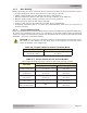
FRONT
VIEW
SIDE
VIEW
~2"
~1"
~½”
0.375" diameter
Cable
~¾”
(~2.54 cm)(~5.1 cm)
(~1.9 cm)
(~1.3 cm)
(~.95 cm)
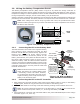
Figure 2-18, Battery Temperature Sensor
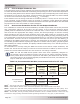
Figure 2-19, BTS and Battery
Cable Hardware Installation
nut
split washer
CAUTION:
Ensure there is
nothing placed
between the
battery cable
ring lug and
battery post.
cable to
controller
(with ring lug)
battery
post
Battery
Temperature
Sensor
inverter cable
(with ring lug)
The BTS should be connected to the negative battery
post. However, when connecting the BTS, the BTS
terminal should NOT be placed directly against the
battery post. Instead, all power cables (charge
controller and inverter) should be placed on the
battery terminal fi rst, then place the BTS terminal on
the power cable terminals. Refer to Figure 2-19 to
stack the battery cable and BTS terminal hardware
correctly. Incorrectly installed hardware causes a high
resistance connection which could lead to poor charge
controller performance, and may melt the cable and
terminal connections.
Info: The BTS terminal can be connected to
either the positive or negative battery post
- electrically, it does not matter. However,
we recommend connecting the BTS to the
negative battery post to help avoid the pos-
sibility of an electrical short.
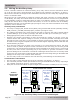
2.8.1 Connecting the BTS to the Battery Bank
2.8.2 Connecting the BTS to the PT Controller
1. After placing the controller negative cable (and inverter battery cable, if used) on the battery
negative post, attach the ring terminal end of the BTS to the battery post.
2. Route the BTS cable to the charge controller following existing communication wire runs.
Info: To prevent electrical interference in the BTS cable, it should not be routed in the
same conduit as the power cables (i.e., PV wiring and battery cables).
3. Connect the RJ11 connector end of the BTS cable to the yellow-labeled BTS port on the charge
controller (Figure 1-2, Item 15).