
PT-100 Manual


Page 41
© 2017 Sensata Technologies
Installation
2.10 Network Wiring
2.10.1 Communications Cables - Provided
The NEC/CEC requires the insulation of all conductors inside the PT controller to be rated for
the highest voltage present. The PT controller is designed to work with voltages up to 240 volts,
therefore, the voltage rating of the communications cables inside the MP enclosure must be rated
for 240 volts or higher to be code compliant. With the purchase of the PT-100, three six-foot,
yellow communication cables with 300-volt rated insulation are provided. These communications
cables—shown below—are provided to make the connections between the PT controller and any
Magnum network device easier and code compliant. DO NOT substitute for the supplied cables
—most cables do not contain the properly rated insulation.
Info: These cables carry less than 30 volts and are thus considered a “limited energy
circuit”, which is normally not required to be installed in conduit.
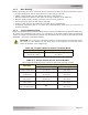
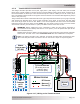
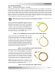
Figure 2-21 shows the ‘NETWORK’ cable. It allows the
PT controller to be networked to a Magnum inverter
and remote. This cable is a 6’ (1.83 m), 4-conductor,
telephone-type with a male RJ14 6P4C (6-position/4-
conductor) connector and a green NETWORK label on
each end. One end of this cable is connected to the
inverter, and the other end is routed to the controller
and connected to the NETWORK port inside the
controller’s wiring area. See Figure 2-24.
Figure 2-21, NETWORK Communication Cable (300V Rated)
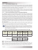
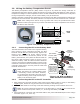
Figure 2-22 shows the ‘EXTENSION’ cable. It allows
the Battery Temperature Sensor (BTS) to be connected
to the controller. This is a 6’ (1.83 m), 4-conductor,
telephone-type cable with a male RJ14 6P4C
(6-position/4-conductor) connector on one end and a
female RJ14 plug on the opposite end. The female plug
connects to the ME-BTS (Battery Temperature Sensor).
After connecting to the ME-BTS, this extension cable
is routed to the controller and connected to the BTS
port inside the controller’s wiring area.
Figure 2-22, Extension Cable (300V Rated)
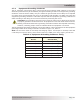
Figure 2-23 shows a ‘STACK’ cable. It allows multiple
controllers to be connected together. This cable is
6’ (1.83m), with a male RJ45 8P8C (8-position/8-
conductor) connector on each end. It comes with 300-
volt rated, yellow insulation. One end of this cable is
connected to one of the STACK ports in one controller,
and the other end is routed to another controller
and connected to one of the STACK ports inside that
controller’s wiring area. See Figures 2-28 and 29.
Note: If NEC/CEC requirements do not apply, a CAT
5 cable (RJ45/8P8C) can be used. However, the CAT
5 cable must be no longer than 6 feet—to prevent
high speed data communication issues.
Figure 2-23, Stacking Cable (300V Rated)