
PT-100 Manual


Page 45
© 2017 Sensata Technologies
Installation
2.11 Stacking Installation - Wiring Multiple PT Controllers Together
A single PT controller can provide up to 100 amps of charging current to the battery bank. When
more charging current is required than can be provided by a single PT controller, up to seven PT
controllers can be connected (or “stacked”) together to increase the charge current capability.
Advantages when Stacking
Rather than having separate and independent controllers charging the same battery bank,
stacking multiple controllers has distinct advantages, such as:
• Coordinated battery charging profi les. The target voltage, charge time and charge mode
are coordinated between each controller—preventing charging confl icts between multiple
controllers on the same battery bank.
• Setup from one convenient place using a networked Magnum inverter and remote.
• Correlates the battery temperature compensation, which means only one BTS sensor is
required for the entire inverter/multi-controller system.
• Correlates data (i.e. current, charge mode and faults) from each PT-100 controller to provide
system information in one place on the system remote.
• Ensures all stacked controllers turn off if a ground fault occurs on a single PT-100 controller.
Stack Installation Requirements
When connecting PT controllers together in a stacked system confi guration, certain installation
requirements have to be met to allow proper communication and charging operation.
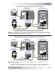
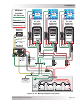
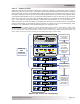
1. Each PT controller must be connected to the same battery bank (see Figure 2-27).
2. The PV input must be connected to its own independent PV array, ensuring that no wires are
interconnected between any charge controller (see Figure 2-27).
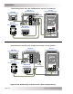
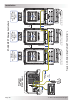
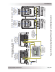
3. Each controller must be connected to each other using a Stacking cable - connected in a daisy
chain style as shown in Figures 2-28 or 2-29.
4. No more than seven PT controllers can be connected together in a stacked confi guration.
5. When multiple controllers are mounted together, there must be at least 1” between each
controller to allow for free air fl ow and to prevent over-temperature conditions. In hot climates,
some additional clearance between units may be needed to prevent thermal derating.
6. One controller (only one controller) in the stacked confi guration must be connected to the
network port on a Magnum inverter, which must also be networked to a Magnum remote (e.g.,
ME-ARC or ME-ARTR) - see Figures 2-28 or 2-29 and Table 2-10.
Note: If using a ME-ARTR, do not connect any PT-100’s directly to the ME-ARTR (see Figure
2-28).
7. DIP switch 10 must be enabled (UP) on each stacked controller (see Figures 2-28 or 2-29).
8. Each PT controller must have it’s own unique network address number (from C01 to C07). Use
DIP switches 7, 8, and 9 to set the network address number on each controller [refer to Figures
2-28 or 2-29 and Section 3.1 (Switches 7, 8 & 9)].
Note: Controller address number C00 is not a valid address number and must be changed to
C01 thru C07 to communicate to other controllers in a stacked confi guration.
Note: The controller confi gured with the lowest network address becomes the master controller
and all other controllers become slave controllers.
9. If a BTS is connected to the inverter, no other BTS is required. When the inverter and controllers
are networked, the inverter’s BTS information will be used to temperature compensate the
inverter and the controller’s charging voltage.
Note: If the BTS is only connected to a controller, the BTS information from the controller will
not be used by the inverter.