
PT-100 Manual


© 2017 Sensata TechnologiesPage 52
Setup
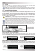
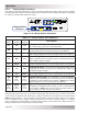
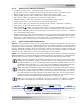
Figure 3-1, DIP
Switch Settings
DEFA ULT SETTING (all switches down)
System Voltage
GFDI Mode
AFP Mode
Battery Type
Absorb Time (address)
Stack Mode
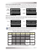
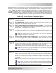
Switch 1: AFP (Arc-Fault Protection) Mode
Normally this switch is DOWN, which enables the Arc-Fault Detection circuitry. This switch can be
set to UP, which disables the Arc Fault Detection circuit to prevent nuisance tripping. See Section
4.6 for more information on the operation of the Arc-Fault Detection circuitry.
Arc-Fault
detection
disabled
(UP)
Arc-Fault
detection
enabled
(DOWN)
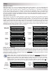
Switch 2: GFDI (Ground Fault Detection and Interruption) Mode
Normally this switch is DOWN (GFDI Enabled). The internal GFDI can be disabled to allow an
external GFDI circuit to be used, the controller to operate with an ungrounded PV array, the battery
negative to be grounded elsewhere in the system, or multiple controllers to be used in the same
PV installation. See Section 4.5 for more information on the operation of the GFDI circuitry.
GFDI
disabled
(UP)
GFDI
enabled
(DOWN)
3.0 Setup
When the PT controller is not connected to a Magnum inverter/remote, the internal DIP switch
(Figure 1-2, Item 4) is used to determine the PT controller’s operation.
Info: When the PT controller is connected and networked with a Magnum inverter and
remote, the remote is used to set up and/or control the PT controller’s operation. Refer
to the appropriate remote owner’s manual for setup information (see Section 2.10.3).
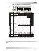
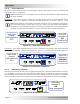
3.1 Adjust DIP Switch Settings
The DIP (Dual In-line Package) switch includes 10 individual slide switches that can be set to the
UP (on) or DOWN (off) position. As a standalone PT controller, the arrangement of the 10 switches
determines the operating parameters. The default setting (all DIP switches DOWN) is adequate
for most installations, however, you have the option to change some of the operating parameters.
This section shows how to change the DIP switch and describes the function of each switch setting
to help you confi gure the PT controller.
CAUTION: The PT controller cannot warn against or disallow incorrect DIP switch settings.
Ensure the settings used to charge the batteries—the Absorption Done Time selection
and the Battery Type selection—are checked carefully against the battery specifi cations.
Incorrect settings may damage the battery or shorten battery life.
Info: When changing any DIP switch, make sure each switch is fully in the UP or DOWN
position as needed. After making a DIP switch change, all power to the PT controller must
be cycled (i.e., removed and reconnected) before a switch setting becomes effective.
Info: If networked, the remote overrides all DIP switches except for switches 1 (AFP), 2
(GFDI) and 10 (Stack) which are hardwired and still active even with a remote connected.