
PT-100 Manual


Page 55
© 2017 Sensata Technologies
Setup
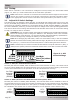
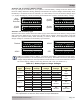
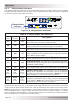
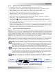
Table 3-2, Summary of DIP Switch Position
DEFAULT SETTING (all switches down)
UP
DOWN
(DN)
Switch Function Switch Position
SW1
ARC Fault
Detection
Enabled SW1 DN
Disabled SW1 UP
SW2
Ground Fault
Detection
Enabled SW2 DN
Disabled SW2 UP
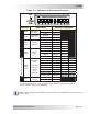
SW3,
SW4
System
Voltage
Auto Detect SW3 DN
SW4 DN
12V System SW3 DN
SW4 UP
24V System SW3 UP
SW4 UP
48V System
SW3 UP SW4 DN
SW5,
SW6
Battery
Type
Flooded
SW5 DN SW6 DN
AGM1 SW5 DN
SW6 UP
AGM2
SW5 UP SW6 UP
GEL
SW5 UP SW6 DN
SW7,
SW8,
SW9
Absorption
Time
(controller
address
number
when
stacked)
Auto Determine SW7 DN
SW8 DN SW9 DN
1 Hour (C01) SW7 DN
SW8 DN SW9 UP
2 Hours (C02) SW7 DN
SW8 UP SW9 UP
3 Hours (C03) SW7 DN
SW8 UP SW9 DN
4 Hours (C04) SW7 UP
SW8 UP SW9 DN
5 Hours (C05) SW7 UP
SW8 UP SW9 UP
6 Hours (C06) SW7 UP
SW8 DN SW9 UP
7 Hours (C07) SW7 UP
SW8 DN SW9 DN
SW10
Stack
Mode
Disabled SW10 DN
Enabled* SW10 UP
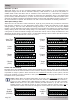
* Switches 7, 8, and 9 are used to determine the stacking address number
of each controller (C01 - C07) when the stack mode switch (SW10) is
set to
the UP position (Stack Mode enabled)
.
Stack address switches*
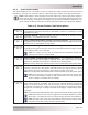
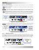
Info: A label showing the information listed in Table 3-2 is attached to the inside of the
access cover.