
PT-100 Manual


© 2017 Sensata TechnologiesPage 62
Operation
4.3 MPPT Operation
The PT-100 charge controller uses Maximum Power Point Tracking (MPPT) to harvest the maximum
possible power from the PV array—under any environmental condition—to charge the batteries.
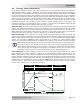
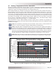
The purpose of MPPT is fi nd the point of the PV array’s operating curve (shown in Figure 4-8)
where the current (I) and voltage (V) are optimized at the same time—referred to as the Maximum
Power Point (MPP). The MMPT algorithm in the PT-100 is designed to sample the output of the
PV array and adjust the load it presents to the PV array until the voltage and current approaches
the MPP. The sampling is continuous in case the PV maximum output power changes because of
environmental conditions, such as panel shading, cloud cover, and panel temperature.
Each morning when the PT controller awakes, a full sweep of the PV array is performed to fi nd
the maximum point. The high effi ciency of the PT-100 to harvest the array’s maximum power is
obtained based on its ability to closely operate at the MPP, its quick response to changes in the
MPP, and the periodic full sweeps to guarantee that it continues to operate at the correct MPP.
When the current the batteries can accept is lower than the PV source can provide, or the
batteries are close to being fully charged and are no longer able to absorb the incoming current,
the controller can no longer operate the panel at its maximum power point. When this happens,
the MPPT algorithm in the PT controller moves the PV panel operating point away from the peak
power point to limit the charging current to the battery.
Night-time PV Array Disconnect
The PT controller includes an automatic night-time disconnect circuit. During night-time periods
when the PV array voltage is lower than the battery voltage, the batteries are prevented from being
discharged into the PV array by an internal switch. This internal switch disconnects the PV array
from the batteries—eliminating the need for a blocking diode between the PV array and the battery.
Note: At night—when the array is not producing power—you may be able to measure some voltage
on the PV input terminals; however, there shouldn’t be any sustained power behind it.
Figure 4-8, I-V Curve
PV Voltage (V)
MPPT Range
Max PV Input
(Damage can occur)
I-V Curve
50
45
40
35
30
25
15
10
5
0
20
60
PV Current (I)
MPP
Representative of a PT-1 00
connected to a 48-volt battery system
High Voc
Range
155 175 195 2552352151351159575