
PT-100 Manual


Page 65
© 2017 Sensata Technologies
Operation
4.4.2 Starting or Stopping an Equalization Charge Cycle
See Table 3-1 to determine the equalize voltage for your battery type. Equalize charging can only
be enabled if the Battery Type setting allows.
Info: Equalization charging is available if FLOODED or AGM 1 is selected as the Battery
Type (DIP switches 5 and 6), it is not available if GEL or AGM 2 is selected.
To start the equalization charge cycle:
1. Make sure PV power is available to the controller, and the controller is charging the batteries
(i.e., BULK, ABSORB or FLOAT LED is on).
Info: If there is not enough PV power available to allow the controller to start charging,
the equalization charge cycle can not be enabled from the front panel.
2. Press the SELECT and RESET pushbuttons simultaneously until the BULK, ABSORB, and
FLOAT LEDs come on in sequence (~2 seconds). These LEDs continue to come on in sequence
throughout the equalization charge cycle.
To stop an equalization charge cycle manually, press the SELECT and RESET pushbuttons
simultaneously until the BULK, ABSORB, and FLOAT LEDs no longer come on in sequence (~2
seconds). Once EQ has stopped, the PT controller returns to the charge stage it was in before
EQ was started. The EQ charge will also stop if PV voltage to the controller is interrupted; if this
happens, the controller will return to the previous charge stage once PV voltage is reconnected.
Info: If multiple PT controllers are connected together (i.e., stacked), see Section
4.13.4 for information on starting or stopping an Equalization charge.
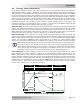
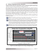
Figure 4-10, Start/Stop Equalize Charge
To start/stop equalize
charge, push SELECT +
RESET for 2 seconds
4.5 Ground Fault Detection and Interruption (GFDI) Operation
The GFDI circuit inside the PT controller has the ability to detect, indicate and interrupt a ground
fault in the PV array, which may be required according to the National Electrical Code 690.5.
If the PV array is wired in a negative grounded confi guration, the internal 0.5 amp GFDI fuse should
provide the PV system’s only negative-to-ground bond and is used to detect PV ground-faults. If
a ground fault current larger than 0.5 A is detected, the GFDI fuse will open, the PT controller will
turn off, and the display will indicate the F12 (Ground Fault) code. After the ground fault has been
located and eliminated and the GFDI fuse replaced, the ground fault code must be cleared (by
pressing the RESET pushbutton for one second) before the controller resumes operation.
The Ground Fault Detection circuit can also be disabled by setting the GFDI switch (DIP switch #2)
to UP. Disabling the GFDI allows the controller to operate with an ungrounded PV array, allows a
single negative-ground connection to be made elsewhere in the system (so that an external GFDI
circuit can be used), and allows multiple controllers to be used in the same PV installation.
If the PT controller’s internal GFDI circuit is required to be disabled, the GFDI fuse must also be
removed. Removing the GFDI fuse opens the negative-to-ground bond within the controller so that
a single negative-ground connection can be made elsewhere in the system—either at the battery
terminal or through an external PV-GFDI circuit connected to the PV wiring. To remove or replace
the GFDI fuse, see Section 5.5.
Info: If multiple PT controllers are connected together (i.e., stacked), see Section 2.11
for information on setting up the GFDI for a multiple controller system.