
PT-100 Manual


© 2017 Sensata TechnologiesPage 66
Operation
4.6 Arc-Fault Protection Operation
Arcs are caused by an intermittent connection and are dangerous because they are not an overload
or short-circuit, so the overcurrent protective device does not operate; however, they can burn
through wiring insulation or ignite nearby combustibles.
The PT controller has an integrated Arc-Fault Protection (AFP) circuit, which provides additional
protection against fi res caused by an arc in the PV system. Arc-fault protection is required according
to the National Electrical Code (NEC) for PV systems operating at a maximum voltage of 80 volts
or greater. In accordance with Section 690.11 of the NEC, the AFP circuit should detect, indicate
and interrupt an arc-fault, and the fault indication should not be able to automatically reset/clear.
After a series arc-fault is detected, the PT controller shuts down and displays a F13 (AFP Fault)
code. Once the PT controller shuts down, the circuit is opened in an attempt to extinguish the
arc-fault in the PV system. When the PT controller has shut down from detecting an arc-fault, it
must be manually reset.
What is a series arc-fault? A “series” arc-fault results when the intended continuity of a current-
carrying conductor, connection, or component in series with the PV string and the load is failing.
This is different from a “parallel” (or short-circuit) arc-fault, which is a short between two current-
carrying conductors, or between a current-carrying conductor and a grounding conductor or other
grounded device. Series arc-faults occur when the PV array is producing current and a connection
in the PV electrical circuit becomes more resistive (i.e., unintentionally starts opening). This can
be caused by damaged conductors, or loose/corroded connections (either inside a PV module or
on a PV system component).
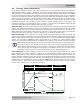
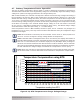
4.6.1 AFP Test Switch
The arc-fault test switch (see Figure 4-11) is provided to determine whether the arc-fault detection
circuit in the PT controller is functioning properly. When the arc-fault test button switch is pressed
and released, a simulated arcing condition is generated and the AFP circuit must be able to detect
this arcing condition and cause the PT controller to shut down.
To perform an arc-fault protection circuit test:
1. First ensure the PT controller is on and operating, PV power is available and connected to the
PT controller’s PV input, and DIP switch 1 is DOWN (ARC fault detection is enabled).
2. Quickly press and release the arc-fault test button switch (under the access cover).
Info: The arc-fault test switch is a small momentary type button switch which operates
by lightly pressing and releasing the top of the switch. Be careful not to apply too much
force to the top or side of the switch when pushing—or the switch might break.
3. The fault LED (red) and ARC fault LED (red) comes on, F13 (AFP Fault) code displays, and the
PT controller shuts down.
4. The PT controller must not resume operation until the AFP fault is manually cleared (either by
pressing the RESET pushbutton for one second, or removing all power from the PT controller).
If all four steps passed, then the arc-fault circuit inside the PT controller is functioning properly.
If the AFP circuit test fails:
1. Ensure there is suffi cient PV power connected to the PT controller’s input—this test cannot be
performed unless there is suffi cient PV power to produce an arc.
2. Ensure the arc-fault detection circuitry is enabled by verifying DIP switch #1 is DOWN.
Figure 4-11, AFP Test Switch
AFP Test Switch
ARC Fault LED
DIP Switch #1 is DOWN