
PT-100 Manual


© 2017 Sensata TechnologiesPage 80
Maintenance and Troubleshooting
Table 5-3, Stack Fault Code Descriptions (continued)
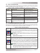
FAULT LED
ON
Stack Switch Fault - The PT controller is not able to run because the controller’s
stacking address has been incorrectly set.
Remedy:
1. Ensure the stacking address is not set to C00.
a. C00 is an invalid stacking address, examine DIP switches 7, 8, and 9 to
ensure that only C01-C07 is set as the stacking address (see Section 3-1,
Switches 7, 8 & 9).
2. Ensure none of the stacked controllers have the same stack address.
a. Each controller must have its own unique stack address. Examine DIP
switches 7, 8, and 9 to ensure each controller address is different—and not
set to C00.
3. If stacking cables have been connected between controllers, ensure stack
mode (DIP switch 10 set UP) has been enabled.
a. Set DIP switch 10 to the UP position (stack enabled) on every controller
connected together in a stacked confi guration.
The fault will automatically clear and the controller will resume operation once the
correct stack address is set.
FAULT LED
BLINKING
Battery Voltage Fault - This fault indicates that there is a large battery voltage
difference between the master controller and a slave controller. This fault is only
allowed on a slave controller and displays on each slave controller that detects a
4% or greater battery voltage difference from the master controller.
Note: The controller continues to run with this fault.
Remedy: This fault can be caused by an open breaker to the BAT+ input,
a bad wire connection, or having a large voltage drop (due to using wire
that is too small for the distance and current) to the BAT input terminals
on the slave PT controller.
The fault will automatically clear and the controller will resume operation
once the voltage to the BAT input terminals (on the slave controller) is
within 4% of the master controller’s battery voltage.