
PT-100 Manual

© 2017 Sensata TechnologiesPage 82
Maintenance and Troubleshooting
Mounting
Bracket
PT-100
Controller
(Electronics
Section)
Remove two
#8/32 x 3/8”
Phillips head
screws
PT-100 Controller
(Wiring/Conduit Box)
Leave in place
Remove two
#8 x ¾”
Phillips head
screws
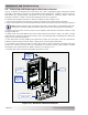
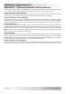
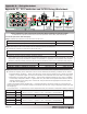
Figure 5-2, Electronics Section Removal
5.6 Removing and Replacing the Electronics Section
The PT controller is designed as a two-piece unit, with a repairable upper electronics section
physically connected to a lower non-serviceable wiring/conduit box—making it easier to service.
This allows any wiring/conduit connected to the PT controller to remain in place, while the
electronics section is easily removed and replaced if service is required.
To replace the electronics section on the PT controller (refer to Figure 5-2):
1. If it has not already been removed, remove the access cover from the PT controller.
2. Mark, then remove any connection between the electronics section and the wiring/conduit box.
Info: Before removing any connection and wires, mark them to correspond with their
component connection and terminals to prevent incorrect wiring when reconnecting.
3. Remove the two lower screws (#8/32 x 3/8” Phillips) that hold the electronics section to the
wiring/conduit box.
4. While using one hand against the front of the electronics section to hold it in place, use the
other hand to remove the two upper screws (#8 x 3/4” Phillips) that are holding the electronics
section to the mounting bracket.
5. Now that all the screws holding the electronics section are removed, it can be removed by
pulling it forward (away from the wall)—sliding it out of the wiring/conduit box.
6. To replace the electronics section, reverse the previous steps—ensuring the upper and lower
screws are correctly secured and all connections are wired correctly, and properly torqued
according to the values shown in Table 2-6 and 2-7 in Section 2.7.3.
7. Perform the power-up test as described in Section 2.12.2.