
PT-100 Manual

Page 90
Appendix D – Sizing Worksheet
Sizing Conductors and Overcurrent Protection Device Ratings in the PV System
To calculate the required conductor and overcurrent protection device sizes, follow these steps:
PV Circuits (PV Source and PV Output):
Step 1) Calculate the maximum current for the PV circuits (l
MAX
):
Max current for PV source (PV
SOURCE
-l
MAX
) = Module l
SC
x 1.25 PV
SOURCE
-l
MAX
) =
Max current for PV output (PV
OUTPUT
-l
MAX
) = PV
SOURCE
-l
MAX
x
# of strings PV
OUTPUT
-l
MAX
) =
Step 2) Determine the PV circuit conductor size for continuous circuit currents (lCONT):
a) Calculate the continuous current for the PV circuits (l
CONT):
Continuous current for PV source (PV
SOURCE
-l
CONT
) = PV
SOURCE
-l
MAX
x 1.25 PV
SOURCE
-l
CONT =
Continuous current for PV output
(PV
OUTPUT
-l
CONT
) = PV
OUTPUT
-l
MAX
x 1.25 PV
OUTPUT
-l
CONT =
b) Find the PV circuit’s conductor sized for continuous current:
Look at Table 310.15 (B)(16) and select the insulation temperature rating column that corresponds to the lowest
temperature rating of any terminal the conductor is terminated on—regardless of the insulation of the selected
conductor. Select the smallest conductor that exceeds the continuous current (lCONT) calculation from Step 2a.
PV circuit continuous current:
PV
SOURCE
-l
CONT
=PV
OUTPUT
-l
CONT
=
Lowest terminal temperature:
Conductor sized to continuous currents: (AWG @Temp) (AWG @Temp)
Step 3) Determine the conductor size for maximum circuit currents derated after adjustment factors
(l
DERATE
):
a) Calculate the ampacity of the conductors in the PV circuits derated by the following “conditions of use” factors:
1. Conduit Fill Factor (Fill Factor) – When more than three current carrying conductors are in conduit (or bundled
together) in continuous lengths >24 inches, then divide by the Conduit Fill Factor from Table 310.15(B)(3)(a).
2. Temperature Correction Factor (Temp Factor) – If the average ambient temperature (Avg. Temp)—in addition
to the Rooftop Temperature Adder*—is greater than 30°C, then these two temperatures become the effective
ambient temperature (Eff. Temp) value. Use this Eff. Temp to determine the appropriate Correction Factor**
from Table 310.15(B)(2)(a).
* Rooftop Temperature Adder (Rooftop Add.) – Conductors/raceways exposed to sunlight on a roof require the
ambient temperature to be increased—based on the distance from the roof—using a temperature adder from Table
310.15(B)(3)(c).
**Correction Factor – to determine the correct temperature factor, the Conductor’s Temperature Rating is required.
Avg. Temp Max PV source circuit current with conditions of use
(PV
SOURCE
-l
DERATE
) = (PV
SOURCE
-l
MAX
÷ Fill Factor ÷ Temp Factor)
PV
SOURCE
-l
DERATE
Rooftop Add. +
Eff. Temp = PV
SOURCE
-l
MAX
= Fill Factor = Temp Factor =
Avg. Temp Max PV output circuit current with conditions of use
(PV
OUTPUT
-l
DERATE
) = (PV
OUTPUT
-l
MAX
÷ Fill Factor ÷ Temp Factor)
PV
OUTPUT
-l
DERATE
Rooftop Add. +
Eff. Temp = PV
OUTPUT
-l
MAX
= Fill Factor = Temp Factor =
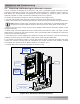
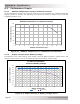
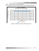
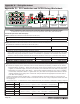
Appendix D – PV Conductor and OCPD Sizing Worksheet
Battery
Breaker
Inverter/
Charger
Battery
Bank
Battery
Breaker
Inverter
AC Panel
PV Circuits: PV Source [1] and PV Output [2]
PV Controller
(PT-100)
Output Circuit
Standalone Inverter
Input Circuit
Standalone Inverter
Output Circuit
PV Source PV Output
.1 .2
.1
.2
.3 .4
.5