
Tech Paper

High Ca pa cit y D C Break e rs I n st ruct ion Sheet
Pa rt N um be r: 6 4 - 0 0 4 0 Rev B 1
Magnum Energy, I nc.
2211 West Casino Rd.
Everett, WA 98204
w w w .m a gnum e ner gy.com
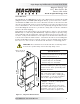
Figure 1 , Physical D im ension s
7.125
(180.97)
8.334
(211.68)
3.828
(97.23)
2.968
(75.39)
1.5
(38.1)
I nt roduction
The BR-DC175 and BR-DC250 are t he sam e DC breakers installed in t he MP
( Magnum Panel) and MMP ( Mini Magnum Panel) system enclosures, and in-
cluded wit h t he MPX ext ensions. These breakers function as the invert er’s DC
disconnect swit ch and can be used as t he bat t ery- t o- invert er circuit prot ect ion
in m ost installations. These breakers were specifi cally designed and t est ed t o
work wit h Magnum invert ers t o provide t he delay t im e needed t o m inim ize
nuisance breaker tripping.
Depending on t he part num ber, t he circuit breaker is eit her a 175 am p ( PN:
BR-DC175) or a 250 am p ( PN: BR- DC250) , high int errupt ion capacity, m ag-
netic-hydraulic, DC circuit breaker. These breakers have front- accessible con-
nect ions, each provided wit h a 3/ 8- 16 capt ive nut. Each breaker includes t wo
3/ 8- 16 Hex head bolt s wit h washers, and a back m ount kit for installing t his
breaker inside MP enclosures. This kit consist s of t wo m ount ing straps and two
# 10- 32 x 3.5” Torx screws to at t ach t he DC breaker to a m ount ing panel.
CAUTI ON : These breakers m ust be m ount ed in a vert ical position
to m eet t he specifi ed t rip current and trip delay curve.
Specifi cat ions
Appr ova ls
UL 489 Listed Branch Circuit- Breaker
CSA Cert ifi ed C22.2 No. 5
•
•
I nt e r rupt ing Ca pa cit y
10,000 am peres at 160VDC
65,000 am peres at 65VDC
•
•
Trip Tim e D e la y
Custom ized Delay 53 ( DC long delay) ,
constructed t o work specifi cally wit h
Magnum inverters.
Re com m ended Tor que :
220 - 230 inch- pounds ( using 3/ 8”
bolt s to connect cables - having ring
lug t erm inals - t o t he 3/ 8- 16 capt ive
nut s on t he copper ext ensions) .
Ph ysical:
Weight : ~ 2.25 lbs. ( 1020 gram s)
Size: See Figure 1
Term inal connect ions: Two Front-
accessible, tinned- copper ext ensions,
each wit h a 3/ 8- 16 x 1” bolt and
washer screwed int o a capt ive nut .
•
•
•
Sizes shown in
inches ( m m )