
Installation Manual

Page 6
© 2014 Magnum Energy, Inc.
Installation
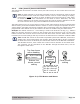
2.4.2 Surface Mount Installation Procedure
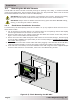
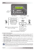
To surface mount, you must use the supplied bezel (Figure 2-4).
Info: The bezel has tabs at the bottom and side that are made with thinner material
(Figure 2-4). They can be cut or broken out to allow the cable to be routed downward
or to the side (Figure 2-6).
1. Using the bezel as a template, mark on the wall the location of the four bezel mounting
screws, and then drill pilot holes for the #8-32 screws.
2. Cut/break the appropriate tab on the bezel for the planned route of the remote cable.
3. Pull the cable through the bezel and place the bezel side with the removed tab over the cable
against the wall.
4. Position the bezel over the drilled mounting holes, and then screw the bezel to the wall using
four of the supplied Phillips screws (Figure 2-6).
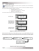
5. Route the other end of the cable to the inverter/charger, and then plug it into the inverter’s
RJ11 REMOTE port (blue label)—inverter has DC power, but is OFF. See Figure 2-2.
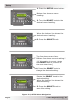
6. Take the other end of the cable and while plugging it into the back of the ME-ARC, view the
remote’s display to ensure the Power-up Self Test initiates (see Section 2.5).
7. If the self test is successful, secure the ME-ARC to the bezel using four of the supplied Phillips
screws. If the self test is unsuccessful, refer to the Section 6.0 “Troubleshooting”.
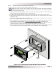
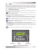
Figure 2-6, Surface Mounting the ME-ARC using the Bezel
Remote
cable