
Installation Manual


Installation
Page 4 © 2017 Sensata Technologies
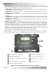
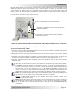
Figure 2-1, System Overview
REMOTE cables (x4) from
router to each inverter’s
REMOTE Port (blue)
Network or
Remote cable
from
ME-AGS-N to
Network Port
(green)
Cables from router to ME-BMK and
ME-ARC, or to ME-AGS-N
#3
MS-PAE
I
NVERTER
(SLAVE 2)
#2
MS-PAE
I
NVERTER
(SLAVE 1)
#4
MS-PAE
I
NVERTER
(SLAVE 3)
#1
MS-PAE
I
NVERTER
(MASTER)
MA
SL1
SL2
SL3
P1 P2 P3
P4
P5 P6
ME-AGS-N
ME-BMK
ME-ARC
Stack cables
(x4) from
router to each
inverter’s
Stack Port
(red)
2.2 Installation Overview
The simplifi ed system diagram shown in Figure 2-1 should be reviewed to assist you with planning
and designing your installation. This drawing is not intended to override or restrict any national
or local electrical codes, nor should it be the determining factor as to whether the installation is
compliant—that is the responsibility of the electrician and the onsite inspector.