
Installation Manual


Setup
© 2017 Sensata Technologies
Page 15
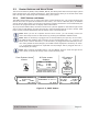
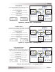
CTRL: 01 AC In Control
The 01 AC In Control menu has four different conditions in which the inverter/charger connects to
an incoming AC power source. Only one may be selected—multiple conditions can be set up and
enabled, but only one can be active at a time.
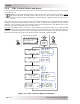
Info: The top status line of the alternates the inverter/charger status with a secondary
AC IN status when AC is present, but is not connecting as a result of a setting made in
the SETUP menu.
Example: AC is present, but Time Connect has been selected from the 01 AC In Control menu
and the current time of day is 6PM. The SETUP menu’s 02C AC In – Time current setting is 2AM-
8AM. The current time of 6PM is outside the connect time, so the inverter/charger will not connect
to the incoming AC until after 2AM. The primary status displays “Inverting” and the secondary
status displays “Time Connect” to let you know the reason that incoming AC has not connected.
• Auto Connect: Automatically connects to incoming AC power when the incoming AC is
qualifi ed by the inverter/charger (voltage is below the high AC input requirements, above
the SETUP button’s 03B Low VAC Dropout setting, and between 50 Hz to 70 Hz for domestic
models; 40-60 Hz for export models).
Info: The Auto Connect setting must be selected if the incoming AC source is a
generator. There is no benefi t from using the AC In feature if the AC source is from a
generator—the generator power may not be available if an AC In feature is activated.
Also, when the generator is turned on (autostarted or manually), it may be prevented
from connecting because the criteria to allow the AC input to connect (AC In is based
on time, VDC, or SOC) may not have been met.
Note: This is true unless using an inverter that has two independent AC inputs—one for
grid and the other for generator (i.e., MSH4024RE), because the AC In Control features
only work with the GRID IN (AC1) input.
• Time Connect: Incoming AC only connects when the time of day is between the Connect and
Disconnect time settings in the SETUP menu’s 02C AC In – Time menu item. See SETUP menu
02C on page 27 for a complete explanation of the Connect/Disconnect time menu settings.
• VDC Connect: Incoming AC only connects when the DC battery voltage falls below the
Connect volts setting in the SETUP menu’s 02D AC In – Volts DC menu item. Disconnects from
incoming AC when the DC battery voltage rises above the Disconnect volts setting, also from
the 02D AC In – Volts DC menu. See SETUP menu 02D on page 28 for a complete explanation
of the Connect/Disconnect volts menu settings.
• SOC Connect: Incoming AC only connects when the battery bank SOC falls below the Connect
setting in the SETUP menu’s 02E AC In – SOC menu item. Disconnects from incoming AC
when the battery bank SOC rises above the Disconnect setting, also from the 02E AC In –
SOC menu. This feature requires the optional ME-BMK (battery monitor) to be installed. See
SETUP menu 02E on page 28 for a complete explanation of the Connect SOC menu settings.
Info: If SOC Connect is selected and the incoming AC connects, the router issues
a one-time “ Start Bulk” command to the inverter/charger. This ensures the charger
enters the Bulk/Absorb charge cycle regardless of battery voltage.
• AC In – Disabled: Disconnects incoming AC when selected. This setting prevents the incoming
AC from connecting to the inverter/charger.