
Magnum ME-PT1 Instructions


ME-PT1 Instruction Sheet
2 © 2014 Magnum Energy, Inc.
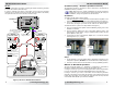
Figure 1, ME-PT1 to ME-AGS-N Installation
12-volt
DC supply
fuse
12-volt
DC supply
fuse
ME-AGS-N
External
Maintain Switch
External
Momentary Switch
ME-RC One time push
(or close): gen runs
for duration of run
time cycle, then stops.
ME-ARC Press switch:
gen runs for 2
minutes, then stops.
Coleman Air Conditioner Zone Control Box
ON
OFF
ME-ARC Switch set
to ON: gen runs until
switch set to OFF.
Switch set to OFF:
gen runs for 2 mins.,
then stops.
ME-RC Switch set to
ON: gen runs until
switch set to OFF.
Switch set to OFF: gen
runs for remaining
duration of run time
cycle, and then stops.
options
PT1-AGS
To Network port on
Magnum inverter
All grounds must be bonded
together to ensure the ME-PT1
works correctly
GEN connection
provides +12VDC
from Zone Control
Box when gen
needs to start.
GEN
connection
GREEN (GND)
WHITE (L2)
BLA CK (L1)
ZONE CONTROL BOX
115 VAC IN
9-PIN PLUG TO
UPPER UNIT
FREEZE R OOM
HEAT
SHED
COOL
SHED
TO USE WITH
LOAD SHED
DEVICE REMOVE
JUMPER A ND
CONNECT TO
N.C. CONTATCT
ROOM
SENSOR
FREEZE SENSOR
ME-PT1
ME-ARC
A. Using a momentary type switch: Pressing the switch causes the generator
to run for two minutes, and then stop.
B. Using a maintain type switch: If the switch is set to ON, the generator
continues to run until the switch is set to OFF. Once the switch is set to OFF,
the generator will run for two minutes, and then stops.
ME-PT1 Instruction Sheet
© 2014 Magnum Energy, Inc. 3
Installation/Setup – ME-AGS-S (Standalone Version)
The following pertains to the ME-PT1 when connected to the ME-AGS-S
(Standalone Version) controller.
Info: Other than the specifi c installation and setup instructions
listed below, refer to the ME-AGS-S Owner’s Manual (64-0004) for
installation, setup, and operation of the ME-AGS-S.
Installation
To prepare the ME-AGS-S remote switch:
1. Find the temperature sensor behind the remote switch’s front plate. It is a
small reddish looking device close to the metal front plate (see Figure 2).
2. Use a pair of small wire cutters to cut open one side of the temperature
sensor wire (see Figure 3). Ensure the cut ends are not able to touch.
To install the
ME-PT1 (
refer to the steps below and Figure 4):
1. Plug a 6-conductor phone splitter into the REMOTE (purple) port on the
ME-AGS-S controller.
2. Plug the ME-PT1 adapter into one of the phone splitter’s ports, and
then plug the remote switch—using its communications cable—into the
phone splitter’s other port.
3. Connect the red wire on the ME-PT1 adapter to a +12-volt DC external
switching device (i.e., switch).
Temperature
Sensor
Temperature
Sensor
(cut open)
Figure 2, Locating Sensor
Figure 3, Sensor Cut Open
Setup
1. On the ME-AGS-S, turn the START TEMP F adjustment clockwise to any
temperature position (DO NOT turn counterclockwise to OFF position).
2. Press the remote switch on the ME-AGS-S to the up (ENABLE) position.
ME-PT1 to ME-AGS-S Operation
The type of external switch (i.e., “maintain” or “momentary”) connected to
the ME-PT1 adapter determines how long the generator can run.
A. Using a momentary type switch: Pressing the switch causes the generator
to run for the duration of the RUN TIME HOURS period, and then stop.
B. Using a maintain type switch: If the switch is set to OFF, the generator
stays off. If the switch is set to ON, the generator runs until the switch is set
to OFF. Once the switch is set to OFF, the generator will not stop until the
current RUN TIME HOURS cycle has been satisfi ed.