MicroGT 500 Inverter Owner’s Manual
Thank you from all of us at Sensata Technologies for purchasing this MicroGT 500 inverter. The MicroGT 500 is a product under the Magnum Energy brand from Sensata. We understand there are many purchasing options in the marketplace, and are pleased that you have decided on a Magnum product. Disclaimer of Liability The use of this manual and the conditions or methods of installation, operation, use, and maintenance of the MicroGT 500 inverter are beyond the control of Sensata Technologies.
Table of Contents Table of Contents 1.0 Introduction ..................................................................1 2.0 Installation ....................................................................2 The MicroGT 500’s Independent DC Inputs .......................... 2 Additional Installation Components to Purchase ................... 3 Required Parts and Tools ................................................. 3 Step 1: Installing the AC Junction Box ................................
Table of Contents List of Figures Figure Figure Figure Figure Figure Figure Figure Figure Figure Figure Figure Figure 1, Basic PV System Installation Diagram ......................... 1 2, MicroGT 500 Dimensions ........................................... 2 3, MicroGT 500s in a PV Array ....................................... 3 4, Attaching and Wiring the Junction Box ........................ 4 5, Attaching MicroGTs to the PV Module Frame ................. 5 6, Connecting MicroGTs to the PV Modules.......
Safety Instructions IMPORTANT SAFETY INSTRUCTIONS This manual contains important instructions to follow during the installation and maintenance of your MicroGT 500 inverter. To reduce the risk of electrical shock and ensure the safe installation and operation of the MicroGT 500, the following symbol appears throughout this document to indicate dangerous conditions and important safety instructions.
Introduction 1.0 Introduction Congratulations on your purchase of a MicroGT 500 inverter. This microinverter is used in utility-interactive grid-tied applications, and the microinverter system is comprised of two key elements: • MicroGT 500 inverter • MagWeb GT unit* Figure 1 is an example of a basic system installation diagram using multiple MicroGT 500 microinverters (and the optional MagWeb GT). * – A MagWeb GT unit is optional, but highly recommended.
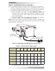
Installation 2.0 Installation You can install individual PV modules in varying combinations of module quantity, orientation, type, and power rate. Refer to Figure 2 for the MicroGT 500’s dimensions. The MicroGT 500 inverters connect with the split-phase grid, and operate with most 60 and 72-cell PV modules. The microinverter auto-senses grid voltage and sets voltage parameters automatically upon initial power up. For more technical information, please see the Specifications section in this manual.
Installation Figure 3, MicroGT 500s in a PV Array Additional Installation Components to Purchase • AC connector cable (PN: ME-MGT-AC-F, x1/branch) • AC extension cable (PN: ME-MGT-AC-EXT, if required) • AC female endcap (PN: ME-MGT-ENDCAP-F, x1/branch) Required Parts and Tools In addition to your PV array and its associated hardware, the following tools are required for assembly: • One AC connection junction box per branch circuit • Mounting hardware suitable for module racking • Sockets and wrenches for
Installation Step 1: Installing the AC Junction Box First, install and wire an AC branch circuit junction box (Figure 4). 1. Install an appropriate junction box at a suitable location on the PV racking system (typically at the end of a branch of modules). 2. Connect the cables to the AC branch circuit junction box. a) Route the open wire ends of the AC connector cable and the AC branch circuit cable (from point of utility) in to the junction box.
Installation Step 2: Attaching the MicroGTs to the PV Frame/Rack 1. Mark the location of each MicroGT 500 inverter on the PV rack— keep in mind the location of the AC branch circuit junction box, or any other obstructions. 2. Mount and attach a MicroGT inverter at each of the identified locations using hardware recommended by the PV module racking vendor (Figure 5).
Installation Step 3: Connecting the MicroGTs to the PV Modules Use Figure 6 when connecting the DC cables from the PV modules to the MicroGT 500 inverters. DC MC4 Connectors Figure 6, Connecting MicroGTs to the PV Modules Note: Upon connecting the DC cables to the first module, the MicroGT 500 inverter’s LED (on bottom of unit) should blink red, followed by three green blinks—indicating that the MicroGT inverter is functioning correctly.
Installation Step 5: Connecting the MicroGTs using AC Connectors WARNING: DO NOT exceed the maximum number of seven microinverters in an AC branch circuit. Note: An AC Extension Connector cable (ME-MGT-AC-EXT) is needed if the microinverters on the same branch circuit are >6 feet apart. 1. Plug the AC Connector cable’s female end (other end hardwired to junction box – Figure 4) into the male AC connector of the first MicroGT.
Installation Step 6: Completing Installation of the MicroGT 500s Each MicroGT 500 microinverter has two removable serial number labels on the front side (Figure 10). Use these serial number labels to create your system’s microinverter array installation map. Note: The unique serial number for each MicroGT is also the ‘Inverter ID’ that is programmed into the MagWeb GT device. For each microinverter: • One label for each channel (i.e., each microinverter powers two panels—A & B). See below.
Operation 3.0 Operation WARNING: Ensure that all AC and DC wiring is correct. Check that none of the AC and DC wires are pinched or damaged. Be sure all the junction boxes are properly closed. Basic MicroGT PV System Operation (w/ MagWeb GT) To operate a battery-less MicroGT 500 inverter PV system: 1. Turn on the AC circuit breaker on each MicroGT inverter branch circuit. 2. Turn on the main utility grid AC disconnect. The system will start producing power after a five-minute wait time (per UL 1741).
Troubleshooting 4.0 Troubleshooting If your PV system does not operate properly, qualified personnel might correct the situation using the troubleshooting info below. Status Indications and Error Reporting The LED on the bottom of the MicroGT assists with troubleshooting. Start up LED: A quick red blink followed by three short green blinks when DC power is first applied to the MicroGT indicates a successful startup. Operation LED: • Flashing Slow Green (10 sec.
Troubleshooting A Non-operational MicroGT Inverter There are two possible overall areas of trouble: • The MicroGT inverter may be having problems, or • The MicroGT inverter is working fine, but is having trouble communicating with the MagWeb GT (if installed). The items below refer to MicroGT inverter issues, not communication issues (addressed in the MagWeb GT manual). A quick way to tell whether the issue is the microinverter or a communication problem with the MagWeb GT: A.
Troubleshooting Replacing a Non-operational MicroGT 500 Inverter 1. Disconnect the MicroGT inverter from the PV module in the order below: a) Disconnect the AC by turning off the branch circuit breaker. b) Disconnect the AC connector(s) from the adjacent inverter(s) in the branch circuit. c) Disconnect the PV module DC MC4 wire connectors from the microinverter to be replaced. d) Remove the MicroGT inverter from the PV array. 2. Install a replacement MicroGT inverter to the rack.
Appendix A – Specifications Appendix A – Specifications MicroGT 500 Specifications Model MicroGT 500 Input Data (DC) Recommended PV Module Power (STC) Range Recommended PV Module Power (STC) Rating MPPT Voltage Range Operation Voltage Range Maximum Input Voltage Startup Voltage Range Maximum Input Current 180 – 310W 180 – 330W 22 – 45V 16 – 52V 55V 16 – 22V 12A (x2) Output Data (AC) Nominal Output Voltage Maximum Continuous Output Power Maximum Output Current Nominal Output Voltage Range Maximum Output
Appendix A – Specifications MicroGT 500 Specifications (Cont.) Features & Compliance Communication Design Lifetime Emissions & Immunity (EMC) Compliance Power Line (PLC) 25 yrs FCC Part15; ANSI C63.4; ICES-003 Monitoring Local monitoring only at this time Safety Class Compliance UL1741, CSA C22.2 No. 107.1-01, NEC2014 690.12 Grid Connection Compliance IEEE1547 * Programmable through the MagWeb GT to meet customer need. ** Dependent on local regulations.
Appendix B – Efficiency Curves Appendix B – Efficiency Curves MicroGT 500 Efficiency-Temperature Curves MicroGT 500 Eff. With Ambient Temp.
Appendix C – An AC Coupled/Battery-Backup PV System Appendix C – Installing an AC Coupled/BatteryBackup PV System AC coupling is the ability to use a battery-based inverter to continue to power loads and charge the batteries during a utility power outage. Creating an AC Coupled System In a basic PV installation, the MicroGT inverters utilize renewable energy to offset power consumption from the utility grid. However, they must shut down during a utility power outage.
Appendix C – An AC Coupled/Battery-Backup PV System ON ON ON ON ON ON ON ON ON OFF OFF 120/240VAC @60Hz OFF OFF OFF OFF OFF OFF OFF OFF OFF Utility Power Disconnect OFF ON 120/240VAC @60HZ Bi-Directional Utility Meter Branch Termination Cap Utility/Grid Power 17 © 2016 Sensata Technologies ON OFF ON OFF ON OFF OFF OFF OFF OFF OFF OFF OFF OFF Junction Box ON ON ON ON OFF OFF ON MagWeb GT ME-MGTADAPTER ON ON ON OFF Router ON OFF ON Main Utility Panel ON ON
Appendix D – Radio Interference Appendix D – Radio Interference Statement FCC compliance: The equipment complies with the limits for a Class B digital device, pursuant to Part 15 of FCC rules, which are designed to protect against harmful interference in a residential installation. The equipment could radiate radio frequency energy, and this might cause harmful interference to radio communications if instructions were not followed when installing and using the equipment.
Appendix E – Warranty & Service Information Appendix E – Warranty & Service Information Limited Warranty Sensata Technologies warrants the MicroGT 500 inverter to be free from defects in material and workmanship that result in product failure during normal usage, according to the following terms and conditions: 1. The limited warranty for the product extends for 25 years— beginning from the product’s original date of purchase. 2.
Appendix E – Warranty & Service Information How to Receive Replacement Service If your product requires warranty replacement, contact either: An authorized service center, at www.SensataPower.com, or, Sensata Technologies at: Telephone: 425-353-8833 Fax: 425-353-8390 Email: MagnumWarranty@Sensata.com • • If returning your product directly to Sensata for replacement: 1. 2. 3. Return the unit in the original, or equivalent, shipping container.
Magnum Energy Products Manufactured by: Sensata Technologies 2211 West Casino Rd. Everett, WA 98204 Phone: (425) 353-8833 Fax: (425) 353-8390 Web: www.SensataPower.