
Installation Manual

© 2016 Sensata Technologies
10
Troubleshooting
4.0 Troubleshooting
If your PV system does not operate properly, qualifi ed personnel
might correct the situation using the troubleshooting info below.
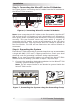
Status Indications and Error Reporting
The LED on the bottom of the MicroGT assists with troubleshooting.
Start up LED:
A quick red blink followed by three short green blinks when DC
power is fi rst applied to the MicroGT indicates a successful startup.
Operation LED:
• Flashing Slow Green (10 sec. interval) – producing power and
communicating with the MagWeb GT.
• Flashing Fast Green (2 sec. interval) – producing power, but not
communicating with MagWeb GT.
• Flashing Red – not producing power.
• Solid Red – microinverter has detected a ground fault (see
below).
GFDI Error:
A solid red LED indicates the MicroGT 500 has detected a DC voltage
Ground Fault Detector Interrupter (GFDI) error in the PV system.
Unless the GFDI error has been cleared, the LED will remain red and
the MagWeb GT will keep reporting the fault. After the ground fault
error is fi xed, follow the instructions in the MagWeb GT Owner’s
Manual to clear this GFDI error.
Other Faults:
Other faults are reported to the MagWeb GT (if installed). Refer to
the MagWeb GT Owner’s Manual for other faults and troubleshooting
procedures.
WARNING: Only qualifi ed personnel should directly handle
the MicroGT 500 inverter.
WARNING: Never disconnect the DC wire connectors when
under load. Ensure that no current is fl owing in the DC wires
prior to disconnecting.
WARNING: Always disconnect AC power before
disconnecting the PV module wires from the MicroGT
inverter. Either disconnecting the appropriate AC circuit
breaker or unplugging the fi rst AC connector of the fi rst
microinverter in a branch circuit is suitable as a means of
disconnection.
WARNING: The MicroGT inverter is powered by PV module
DC power. AFTER disconnecting the DC power—when
reconnecting the PV modules to the microinverter—be sure
to watch for the four short LED fl ashes (x1 red, x3 green).