
Installation Manual


© 2016 Sensata Technologies
1
Introduction
1.0 Introduction
Congratulations on your purchase of a MicroGT 500 inverter. This
microinverter is used in utility-interactive grid-tied applications, and
the microinverter system is comprised of two key elements:
• MicroGT 500 inverter • MagWeb GT unit*
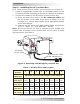
Figure 1 is an example of a basic system installation diagram using
multiple MicroGT 500 microinverters (and the optional MagWeb GT).
* – A MagWeb GT unit is optional, but highly recommended.
Figure 1, Basic PV System Installation Diagram
MicroGT 500 microinverters maximize PV energy production
Each PV module has individual Maximum Power Point Tracking
(MPPT) controls, which ensures that the maximum power is exported
to the utility grid regardless of the performance of the other PV
modules in the array. When PV modules in the array are affected
by shade, dust, orientation, or any situation in which one module
under-performs compared with the other units, the MicroGT 500
inverter ensures top performance from the array by maximizing the
performance of each module within the array.
More reliable than centralized or string inverters
The distributed MicroGT system ensures no single point of system
failure exists across the PV array. MicroGT 500 microinverters are
designed to operate at full power at ambient outdoor temperatures
of up to 149°F (65°C)—see Appendix B – Effi ciency Curves (Figure
11). The microinverter housing is designed for outdoor installation
and complies with the NEMA 6 environmental enclosure rating.
ON
OFF
ON
OF F
ON
OF F
ON
OFF
Main Utility
Panel
Utility/Grid
Power
Utility Power
Disconnect
Bi-Directional
Utility Meter
120/240VAC
@60Hz
120/240VAC
@60HZ
MagWeb
GT*
ON
OF F
ON
OF F
ON
OF F
ON
OF F
ON
OF F
ON
OF F
ON
OF F
ON
OF F
ON
OF F
ON
OF F
ON
OF F
ON
OF F
Router
Junction
Box
Branch
Termination Cap
ON
OF F
ON
OF F
ON
OF F
ON
OF F