ME-ARC Advanced Remote Control Owner’s Manual (Version 4.
Disclaimer of Liability The use of this manual and the conditions or methods of installation, operation, use, and maintenance of the ME-ARC are beyond the control of Magnum Energy, Inc. Therefore, this company does not assume responsibility and expressly disclaims liability for loss, damage or expense, whether direct, indirect, consequential or incidental, arising out of or in any way connected with such installation, operation, use, or maintenance.
Safety Information Important Product Safety Instructions This manual contains safety instructions that must be followed during the installation and operation of this product. Read all instructions and safety information contained in this manual before installing or using this product. Safety Symbols To reduce the risk of electrical shock, fire, or other safety hazard, the following safety symbols have been placed throughout this manual to indicate dangerous and important safety instructions.
Table of Contents 1.0 2.0 Overview.............................................................................................. 1 Installation .......................................................................................... 2 2.1 2.1.1 2.1.2 2.1.3 2.2 2.2.1 2.3 2.4 2.4.1 2.4.2 2.5 3.0 Pre-Installation ............................................................................................ Installation Guidelines .............................................................................
Table of Contents (Cont.) 7.2.3 7.2.4 7.2.5 7.2.6 7.3 7.3.1 7.3.2 7.3.3 7.3.4 7.3.5 8.0 8.1 8.2 8.2.1 8.2.2 8.2.3 8.2.4 8.3 8.3.1 8.3.2 9.0 9.1 9.2 9.2.1 9.2.2 9.2.3 9.2.4 9.3 9.3.1 9.3.2 10.0 10.1 10.2 10.2.1 10.2.2 10.2.3 10.2.4 10.3 10.3.1 10.3.2 A-1 B-1 B-2 Monitoring the AGS .....................................................................................73 Starting and Stopping the Generator..............................................................77 AGS Menu Maps ........................
List of Figures Figure Figure Figure Figure Figure Figure Figure Figure Figure Figure Figure Figure Figure Figure Figure Figure Figure Figure Figure Figure Figure Figure Figure Figure Figure Figure Figure Figure Figure Figure Figure Figure Figure Figure Figure Figure Figure Figure Figure Figure Figure Figure Figure Figure Figure Figure Figure Figure 1-1, Front Panel Features ..................................................................................... 1 2-1, Remote Cable ...........................
List of Figures (Cont.) Figure Figure Figure Figure 10-6, 10-7, 10-8, 10-9, PT PT PT PT Charge Controller METER Menu Map ...................................................... Charge Controller SETUP Menu Map ....................................................... Charge Controller SETUP Menu Map ....................................................... Controller Fault Message (Example) .......................................................
Overview 1.0 Overview The ME-ARC remote control allows you to monitor and customize the operating parameters for your Magnum inverter/charger. This remote can be used on all Magnum inverter/charger models so there is no cross-platform confusion. The ME-ARC50 comes standard with a 50-foot, 4-conductor (twisted-pair) telephone cable and includes non-volatile memory (preserves adjustable settings, even if power to the remote or inverter is removed). Info: This manual is for a ME-ARC with software version 4.
Installation 2.0 Installation Review this section and the Important Product Safety Instructions on page ii before proceeding with the installation of your remote. WARNING: Installations should be performed by qualified personnel, such as a licensed or certified electrician. The installer determines which safety codes apply and ensures all applicable installation requirements are followed. Applicable installation codes vary depending on the specific location and application.
Installation 2.2 Connecting the Remote Cable The ME-ARC comes with a remote cable to enable communication between the inverter and the remote. The cable is a 50-foot, 4-conductor, round twisted-pair, telephony standard with 6P4C (6-position/4-conductor) connectors on each end. When the 6P4C connectors are held side by side with both of the connector tabs facing the same way, the color of the conductors in each connector is the opposite from top to bottom (as shown in Figure 2-1).
Installation 2.3 ME-ARC Remote and Bezel Dimensions Use the information below (Figures 2-3 and 2-4) in preparation for mounting the ME-ARC remote and the bezel (if applicable). Directions for mounting both follow in Section 2.4. ~1⅝" (4.1 cm) 5 ¼” (13.3 cm) ~1" (2.5 cm) 3 ¼” (8.3 cm) 3 ⅞" (9.8 cm) 2 ¾” (7.0 cm) .9" (2.3 cm) 1 ⅛” 5 ⅞" (14.9 cm) (2.9 cm) 1 ½” (3.8 cm) Figure 2-3, ME-ARC Remote Dimensions ~1 ½" (3.8 cm) 5 ⅞" (14.9 cm) 5 ¼" (13.3 cm) 4 ⅜" (11.1 cm) 2 ⅞" (7.3 cm) 2⅞" (7.
Installation 2.4 Mounting the ME-ARC Remote The ME-ARC can either be flush mounted (through an opening in the wall), or surface mounted using the provided bezel. Find a location that is clean, dry and protected. Allow room to access the remote’s SELECT knob and to view the LEDs/display. CAUTION: Ensure that no AC power is connected to the inverter, and then according the your inverter owner’s manual correctly connect the inverter to the batteries.
Installation 2.4.2 Surface Mount Installation Procedure To surface mount, you must use the supplied bezel (Figure 2-4). 1. 2. 3. 4. 5. 6. 7. Info: The bezel has tabs at the bottom and side that are made with thinner material (Figure 2-4). They can be cut or broken out to allow the cable to be routed downward or to the side (Figure 2-6). Using the bezel as a template, mark on the wall the location of the four bezel mounting screws, and then drill pilot holes for the #8-32 screws.
Installation 2.5 Power-up Self Test Info: All power to operate the remote control is provided by the inverter/charger through the remote cable. When the ME-ARC is first connected to an inverter, a power-up self test is initialized. During the self test, the LCD automatically displays in sequence: • “MAGNUM ENERGY Self Test”, then • “(C)2010-2013, Connecting to...”, and then • “ME-ARC V 4.0, INV/CHG V #.#” The remote’s LEDs also change with the screens (see Figure 2-7).
Setup 3.0 Setup When the remote is connected to a Magnum inverter/charger, the settings in the remote control determine the inverter/charger’s operating parameters. The default settings in the remote control are adequate for most installations (see Table 3-3); however, you have the option to change some of the operating parameters. This section shows you how to navigate the remote and gives you an understanding of the function of each adjustable setting. 3.
Setup 1. Press the SETUP menu button. Float Charging 01 System Setup Bottom line shows a menu heading. 2. Turn the SELECT knob to the desired menu heading. Float Charging 02 Invert Setup 02A Search Watts 5 Watts When the bottom line shows the desired menu heading: 3. Press the SELECT knob. Top line shows menu item. Bottom line shows current setting.* *[If this setting is correct, rotate the SELECT knob to continue to the next menu item.] 4. Press the SELECT knob to change the desired setting.
Setup 3.2 Remote Buttons and Menu Items The five menu buttons (FAVS, CTRL, METER, SETUP, or TECH) allow the inverter/charger system to be configured to your specific preferences. These buttons also allow you to access menu items that can help with monitoring and troubleshooting your system. Refer to Figure 3-2 for an example on how to navigate the remote. This section covers each menu button’s function and its various configurable settings. This helps optimize the operation of the inverter/charger. 3.2.
Setup Float Charging DC 13.34V + 0A LCD Display Rotary SELECT Knob FAVS Button Top line shows current FAVS menu and position in FAVS menu. FAVS Press To select a FAVS item F1 Search Watts 5 Watts Bottom line shows current setting. Note: These are default selections that you can change.
Setup 3.2.2 CTRL (Control) Button and Menus The CTRL button accesses the 01 ACIn Control, 02 CHG Control, 03 Gen Control and 04 PT Control menus. Info: An AGS controller or PT charge controller must be connected in order for those device-specific menus under the 03 Gen Control or 04 PT Control settings to display, respectively—unless the TECH: 07 Show all Menus menu has been set to “YES”. Refer to Section 3.2.5 for more information on the TECH 07 menu.
Setup CTRL: 01 ACIn Control 01 ACIn Control menu has four different conditions in which the inverter/charger will connect to an incoming AC power source. Only one may be selected at any one time—multiple conditions can be enabled, but only one can be active.
Setup CTRL: 02 CHG (Charge) Control 02 CHG Control enables you to set the charge mode to Multi-Stage, Start Float, or to Start Bulk. Generally, the charger should be left in the Multi-Stage setting, but to override this setting use the CTRL button and the 02 CHG Control menu. The charger can be forced to start the Float or Bulk mode using the Start Float or Start Bulk settings from the CTRL: 02 CHG Control menu.
Setup 3.2.3 METER Button and Menus The METER menu button gives you access to the various meters that determine the status of the inverter/charger and battery system (AGS, BMK, ACLD, and PT controller also if connected). Info: Depending on the inverter, some meter functions may not be accessible. Refer to Appendix A for more information. Info: Most displays automatically return to the remote’s home screen five minutes after the last button push.
Setup • 02B Load Amps (MS-PAE, MS-PE and MSH models only) – This meter displays the total AC current delivered to the loads on the inverter’s AC output terminals. A positive (+) Load Amps value indicates power is being pulled from the inverter to run an AC load—either using the batteries in Inverter mode, or from the AC input source in Standby mode.
Setup INVERT MODE Current from the battery is used by the inverter to power the inverter’s AC loads. Example below: Current to inverter input (AC Input) = 0 Amps AC Current from battery (Inv/Chg Amps) = -10 Amps AC Current to power the AC loads (AC Load) = 10 Amps AC 02C Input Amps 02D Inv/Chg Amps 0 Amps AC -10 Amps AC AC Input = 0 Amps AC DC CURRENT (BATTERY) -120ADC AC CURRENT (GRID/GEN) MAGNUM INVERTER A FROM BATT .
Setup METER: 03 Timers • 03A Charge Time – This meter displays the total time the charger is holding the batteries at a high voltage level—defined as 0.2 volts greater than the float voltage setting. The timer counts when in the Bulk, Absorption, or Equalization charge stages (or in the Constant Current and Constant Voltage charge stages if CC/CV is selected under the SETUP: 03C Battery Type menu). The meter does not accumulate time when in Float, Charger Standby, Full, or Silent mode.
Setup Top line shows current status SETUP Status... 01 System Setup Press Bottom line shows current SETUP menu heading Rotate to access these: Press to select SETUP menu 02 Invert Setup 05 BMK Setup 03 Charger Setup 06 PT Setup 04 AGS Setup Figure 3-9, SETUP Button and Menus SETUP: 01 System Setup The following menus are used to set up the remote’s screen and clock. • 01A Set Clock – The ME-ARC contains a real time clock that must be set for proper operation of some features.
Setup • 01C Temp Display – This menu item selects whether to display temperatures in Fahrenheit or Celsius. Once you select either Fahrenheit or Celsius, the following menu items will use your selection: the METER: 04D AGS Temp menu, the SETUP: 04E Gen Run Temp menu, and the TECH: 01 Temperatures menu.
Setup Where should I set Search Watts? The Search Watts setting should be adjusted to the same power level (or the next lower setting) of the smallest load that you plan to run. If you don’t know the wattage of the smallest load, turn the switch for the load on and decrease the Search Watts setting until the load comes on and stays on. Info: Even though the Search Watts feature is on, some connected equipment—even if they are off—may draw enough current to keep the inverter in Inverter mode (i.e.
Setup • 02C AC In - Time – This feature allows you to connect to the local power utility at a predetermined time of day. When the current time falls within the set times, the inverter/charger connects to the AC that is connected to the AC input terminals. Once outside the set times, the inverter/charger disconnects from the AC source.
Setup Where should I set AC In - VDC? Check with your battery manufacturer to determine the correct settings for your batteries. Typically, manufacturers do not recommend discharging the batteries below 50% (i.e., a voltage setting of approximately 12.0-12.2 VDC, 24.0-24.4 VDC and 48-48.8 VDC for 12, 24, and 48-volt batteries, respectively). To protect the batteries from overdischarging, set to 12.2 VDC (12v), 24.4 VDC (24v), or 48.8 VDC (48v).
Setup Notes on using the AC In control settings based on VDC or SOC: 1. The AC In - VDC or AC In - SOC settings allow you to optimize the use of another energy source (i.e., solar, wind, and/or hydro), and only allow the use of the utility power when the energy source is not able to keep up with the load demands under normal conditions (i.e., cloudy day). 2. The energy source should be sized to meet the daily power requirements of the loads being operated under normal conditions.
Setup CAUTION: Unless you have an MS Hybrid Series inverter/charger—which has the Load Support feature—the AC Input Amps setting only limits the current to the battery; it does not limit the current to the inverter loads. If the current from the loads on the output of the inverter is greater than the circuit breaker rating on the incoming AC source, you will experience nuisance tripping.
Setup Settings for MSH4024RE: Info: The MSH4024RE is a dual input source inverter/charger having two independent AC source inputs (AC1/GRID and AC2/GEN) with independent VAC Dropout settings for each input. The Set VAC Dropout menu only displays both the AC1 and AC2 fields if the remote is connected to a MSH4024RE model. ◊ Set VAC Dropout (AC1 and AC2) – The AC1 setting determines at what AC voltage—from the AC1 to NEUT terminals—the inverter/charger will connect to or disengage from the incoming AC.
Setup Table 3-1, Battery Type to Charge Voltages (fixed voltage) Battery Type Inverter Voltage 12 VDC Absorption Voltage 14.1 VDC Float Voltage 13.6 VDC Equalization Voltage 14.1 VDC1 GEL 24 VDC 28.2 VDC 27.2 VDC 28.2 VDC1 48 VDC 56.4 VDC 54.4 VDC 56.4 VDC1 12 VDC 24 VDC 14.6 VDC 29.2 VDC 13.4 VDC 26.8 VDC 15.5 VDC 31.0 VDC 48 VDC 58.4 VDC 53.6 VDC 62.0 VDC 12 VDC 14.3 VDC 13.1 VDC 15.5 VDC 24 VDC 28.6 VDC 26.2 VDC 31.0 VDC 48 VDC 12 VDC 57.2 VDC 14.5 VDC 52.4 VDC 13.
CURRENT & VOLTAGE Setup Constant Current Max Charge Amps Constant Voltage Silent Constant Current CV Charge Volts CV Charge Done (= Time or Amps) Recharge Volts (restarts Constant Current charge) Current Voltage TIME Figure 3-10, CV Charge Done Time/Amps Stages (INV/CHG) ¤ Set CV Charge Done – These selections determine when the second stage of charging (Constant Voltage) is finished.
Setup Table 3-2, Battery Amp/Hrs Capacity to Suggested Absorb Time Battery A/H Capacity Suggested Absorb Time Battery A/H Capacity Suggested Absorb Time 200 to 300 1.0 Hrs 1310 to 1500 4.0 Hrs 310 to 500 1.5 Hrs 1510 to 1700 4.5 Hrs 510 to 700 710 to 900 910 to 1100 2.0 Hrs 2.5 Hrs 3.0 Hrs 1710 to 1900 1910 to 2100 2110 to 2300 5.0 Hrs 5.5 Hrs 6.0 Hrs 1110 to 1300 3.5 Hrs 2310 to 2500 6.5 Hrs Continuing to charge past this level may overcharge the batteries.
Setup CURRENT & VOLTAGE Constant Current Max Charge Amps Constant Voltage CV Charge Volts Hold CV Charge Volts Current Voltage TIME Figure 3-11, Hold CV Chg VDC Charge Stages (INV/CHG) * Hold CV Chg VDC – This setting holds the battery voltage at the CV Charge Volts setting. This is for a system that requires a constant charge voltage to be present at all times (see Figure 3-11).
Setup • 03D Absorb Done (Time, Amps, SOC) – This setting identifies whether time, amps, or SOC are used to determine when the second stage of battery charging (Absorption) is finished. The charge cycle transitions to the final charge stage (03G Final Charge Stage) afterwards. Absorption is the second stage of the charge process that attempts to fully charge the batteries.
Setup ◊ Set Absorb Done (SOC) – This setting can be used if a battery monitor kit is installed and you want to use the SOC (State of Charge) of the battery bank to determine when the batteries are fully charged. During the Absorption charge mode, once the METER: 05B Battery SOC menu reaches the Absorb Done SOC setting, the charger transfers to the final charge stage (see 03G Final Charge Stage).
Setup CAUTION: The C/5 or C/20 charge rate settings are not requirements on how to set your battery charge rate. For specific charge rate requirements, refer to your battery manufacturer. CAUTION: If multiple inverter/chargers are used on a single battery bank, ensure that the total charge rate from all inverter/chargers is limited to the maximum charge rate needed for your battery bank. The Max Charge Rate setting only limits the charging on each inverter/charger individually, not on all inverter/chargers.
Setup Final Charge Stage: Multi-Stage First Stage CURRENT & VOLTAGE Bulk Charging Max Charge Amps Final Stage Second Stage Full Charge Absorb Charging Float Charging Float Volts Absorb Volts Absorb Done (= Time, Amps or SOC) ReFloat Volts (restarts Float Charging for 4 hours, then back to Full Charge) Current Voltage TIME Figure 3-12, Final Charge Stage – Multi-Stage CURRENT & VOLTAGE Final Charge Stage: Float First Stage Second Stage Final Stage Bulk Charging Absorb Charging Float Charg
Setup Info: When Multi is selected and the charger goes to Full charge mode, if another charge source (such as PV or wind) is charging the batteries above the fully charged voltage, the charger will remain in the Full Charge stage. Why should I use Multi? Multi is the most commonly used charge mode. It is suitable for most applications and assures a full charge to the batteries, without overcharging.
Setup 3.2.5 TECH Button and Menus The TECH menu button provides access to selections that are used to assist service technicians in troubleshooting. It also provides access to system information along with a selection that allows all system settings to be returned to their original factory default values. See Figure 3-15 below.
Setup TECH: 03 Inv Model Displays the model number of the connected Magnum inverter. Info: When the 03 Inv Model menu item displays “Unknown”, the remote is unable to determine the inverter model. This happens when the remote is connected to a later/ newer inverter model not recognized by an older remote. All remote menu selections and features that are available in the inverter will function normally. Info: When an inverter is stacked in parallel or series, a stacking indication follows the model number.
Setup TECH: 05 SETUP PIN This menu sets the password (PIN – Personal Identification Number) and locks/unlocks the ARC’s SETUP button menus. Why should I use the PIN feature? Restricting access to the SETUP menus with a password can avoid unauthorized changes to your settings by inexperienced users. Setting a PIN (unlocked SETUP button) If a PIN has not been set, the SETUP menus are accessible to everyone (i.e., SETUP unlocked).
Setup Resetting/Clearing a PIN You can override a previously entered PIN. When “PIN = 0***” displays, press and hold the SELECT knob until “PIN = 0000” displays (approximately 7 seconds). Enter a new PIN number. TECH: 06 Ext Control External Control is a read only menu. Magnum Energy has adopted an open protocol policy which allows certain functions of the inverter/charger to be controlled externally—such as with a third party communications device.
Menu Maps 4.0 Menu Maps: ME-ARC Remote Control Figures 4-1 through 4-5 are an overview of the settings and information displays available from the ME-ARC’s menu buttons. Note: When applicable, battery voltage defaults and ranges are shown for a 12-volt battery (24-volt systems multiply by 2; 48-volt systems multiply by 4). FAVS F1 Search Watts R 5 Watts F3 AC Input Amps = 30A F2 LBCO Setting 20.
Menu Maps SETUP [Status/Fault] 01 System Setup P R 01A Set Clock 11:18 AM P Set Clock Hour = 11:18A Minute = 11:18AM P AM-PM = 11:18AM 12:00AM-11:59PM 01B Screen Setup Press SELECT P R Set Screen Setup Brightness= 50% R Range: 0-100% P Set Screen Setup Contrast = 100% R Range: 0-100% Set Screen Setup P Pwr Save=15 Min R Range: OFF, 1-60 Min 01C Temp Display Fahrenheit P Set Temp Display Fahrenheit R Celsius 01D Max Charge Amps = 200 ADC P Set Max Charge Amps = 200 ADC R Range: OFF, 20-990ADC
Menu Maps SETUP continued….
Menu Maps SETUP continued…. [Status/Fault] 03 Charger Setup P continued…. 03D Absorb Done Time = 2.0 Hrs P Set Absorb Done Time R Set Absorb Done Amps R R Set Absorb Done SOC R P Set Absorb Done Time = 2.0 Hrs R 0.1-25.5 Hrs P Set Absorb Done Amps = 20 ADC R 0-250 ADC P Set Absorb Done SOC = 100% R 50%-100% 03E Max Charge Rate = 100% P Set Max Charge Rate = 100% R 0%-100% 03F Max Charge Time = 12.0 Hrs P Set Max Charge Time = 12.0 Hrs R OFF, 0.1-25.
Menu Maps TECH continued…. 03 Inv Model [Inverter model#] Read Only display 04 Fault History Press SELECT Read Only displays R P *Specific fault listed; if no fault, “No Fault History” displays [Fault]* P H1 D0 HH:MM 04A Inv Faults Press SELECT R R Note: Refer to Section 3.2.5 for an explanation of displayed data on each screen [Status] VDC BTS: Tfmer: FETs: ADC ###F ###F ###F 04B AGS Faults Press SELECT Refer to Section 7.2.3.
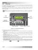
Operation 5.0 Operation This section explains how to operate the inverter/charger using the ME-ARC remote. It also provides information on the LED indicators and the LCD display that are used to show the operational status of the inverter/charger. 5.1 Front Panel The ME-ARC’s front panel contains LED indicators and a LCD display for viewing system status, buttons to control system operation, and a rotary knob that enables you to locate and select system information and settings.
Operation 5.1.4 Menu Buttons These five buttons provide quick access to menu items for configuring, monitoring, and troubleshooting your inverter/charger system. • FAVS – This button allows five menu items to be stored for easy access without having to find them within the SETUP or other buttons. The five items stored under the FAVS button become the “favorite” menus that are most often used. For more information, see Section 3.2.1.
Operation 5.2.2 Charger Mode Turning the charger on: The charge mode is automatically activated and begins when acceptable AC power (utility/generator) is connected to the input of the inverter. When in charge mode, the display may show: Charging, Bulk Charging, Absorb Charging, Float Charging, Full Charge, Silent, Charger Standby, Force Float, Equalizing, Load Support VDC, and Load Support AAC.
Operation 5.3.1 Inverter Mode Status Messages There are six Inverter mode messages. View the top line of the LCD display and the corresponding message in this section to identify and understand the particular Inverter mode. • Inverting – The inverter is providing AC voltage on its output by inverting power from the batteries. • Inverter Standby – The inverter is on but not actively providing power.
Operation Info: Press the ON/OFF CHARGER button to enable charging again. When enabled, the charger continues in the previous charge mode and the CHG (green) LED comes on. • Charging – Once Charger mode has been enabled, the unit waits and displays “Charging” to determine the charge routine. If the DC voltage is low (≤12.8 VDC/12v models, ≤25.6 VDC/24v models, or ≤51.2 VDC/48v models), the charger initiates bulk charging. If the DC voltage is high (≥12.9 VDC/12v models, ≥25.7/24v models, or ≥51.
Operation • Full Charge – This status indicates that you have entered the Battery Saver™ mode. This mode maintains the batteries without overcharging, and prevents excessive loss of water in flooded batteries or drying out of GEL/AGM batteries. After four hours of float charging, the charger turns off and “Full Charge” displays (charger is now in Battery Saver™ mode). If the battery voltage drops to ≥12.6 (12-volt models), ≥25.2 (24-volt models) or ≥50.
Operation • Time Connect – AC power is present at the inverter’s AC input, but the time of day needs to fall within the Connect time and the Disconnect time settings per the SETUP: 02C AC In - Time menu in order for the inverter/charger to connect to the incoming AC. • VDC Connect – AC power is present at the inverter’s AC input, but the battery voltage needs to fall below the Connect Volts setting from the SETUP: 02D AC In - VDC menu in order for the inverter/charger to connect to the incoming AC.
Operation • FET Overload – This fault message indicates the inverter/charger was running normally, but the temperature of the FETs (Field Effect Transistors) started rising abnormally fast. Remedy: Allow the inverter to cool down, then press the remote’s INVERTER ON/ OFF pushbutton (manual restart) to resume operation. If the fault returns, perform an inverter reset (see Section 6.2). If the fault continues, disconnect all the inverter’s AC output wires and perform a power reset (Section 6.3).
Operation • Overcurrent – This fault may be the result of an excessive AC load and causes the inverter to shut down to protect internal power components. If the overload condition lasts for less than 10 seconds, the unit automatically restarts and resumes operation. However, if the overcurrent condition occurs for more than 10 seconds, the unit shuts down and requires a manual restart.
Operation 5.3.4.1 Stacking Fault Messages A fault condition may occur when multiple inverters are connected or stacked together. • StackClock – There is a stacker cable problem; or, one inverter is losing synchronization with the other inverter. Remedy: Ensure you are using the correct stacking cable (the cable for stacking is not a telephone/data cable, it is a custom made cable).
Operation 5.3.5 LED Indicator Guide Use the LEDs and the LCD display to determine the operating status. Table 5-1, LED Indicator Guide LED PWR (green) FAULT (red) CHG (green) INV (green) Page 55 Status Meaning 1) Inverter is disabled; 2) Remote’s in Power Save mode – press any button to activate LEDs; 3) No power to remote OFF (check remote cable or the power to the inverter); or, 4) No AC power at the inverter’s AC output terminals.
Troubleshooting 6.0 Troubleshooting The remote may not be functioning correctly, use the following table to help find a solutions. Table 6-1, Remote Control Troubleshooting Guide Symptom Possible Cause Solution Display shows unrecognizable letters or symbols Static electricity may have been discharged into the LCD display. Refresh Display: Press and hold the SELECT knob for 10 seconds.
Troubleshooting 6.1 Troubleshooting Tips 6.1.1 Inverter Problems • Inverter turned on, green LED on inverter blinking, no output: Inverter is in Search mode. Either defeat Search mode, if not needed, or turn on loads greater than the Search Watts setting. 6.1.2 Charger Problems • Unit won’t transfer to Charge mode with AC applied: Is the charge (CHG) LED on the remote blinking? If not, the charger does not recognize the incoming AC as being within acceptable limits.
Using an AGS Module: Setup 7.0 Using a ME-AGS-N Controller The AGS menus on the ME-ARC remote allow you to customize and monitor operating parameters, and to help troubleshoot your autostart/autostop generator system. IMPORTANT: The AGS must be a connected network version (ME-AGS-N) and communicating with the ME-ARC in order to set up and/or control its operation.
Using an AGS Module: Setup 7.1 Setting Up the AGS using the ME-ARC Press the SETUP button on the ME-ARC remote, and then rotate the SELECT knob to the 04 AGS Setup display. The menus available from this screen allow the generator to be automatically started and stopped based on many different conditions. From Table 7-2, determine the specific autostart and autostop conditions with which you want the generator to be automatically controlled, and then use that specific menu setting to configure the AGS.
Using an AGS Module: Setup SETUP: 04A Gen Run VDC Menu This menu provides the option to start the generator when the battery voltage gets low, and to stop the generator either when the battery reaches a higher voltage level or when the battery has been fully charged and goes into the Float charge stage. Using voltage to automatically start and stop the generator is considered the simplest and easiest method to understand.
Using an AGS Module: Setup • Set Stop Gen Volts – This setting will stop the generator when the battery voltage (on Terminals #3 & #4) increases to or above this setting continuously for the duration of the Stop Volts Delay setting. To allow the battery bank to go through a full Bulk and Absorption charge, this setting should be set to Float. Default setting: 14.4 VDC (12v), 28.8 VDC (24v), 57.6 VDC (48v) Range: OFF, 9.1-16.0 VDC (12v), 18.2-32.0 VDC (24v), 36.4-64.
Using an AGS Module: Setup SETUP: 04B Gen Run Time Menu This menu autostarts and autostops the generator based on a specific time of day. This feature uses the ME-ARC’s internal clock to start and stop the generator at the selected times. Info: Ensure the remote’s clock is correct. If needed, refer to the Section 3.2.4 for guidance on setting the time on the remote’s clock. Info: The ME-ARC clock is powered from the inverter through the remote cable.
Using an AGS Module: Setup Why would I use Gen Run Amps? This feature is designed to prevent the battery from being heavily discharged by monitoring the battery current used to power the inverter loads (shown in AC amps). When the AC current exceeds the Start Gen AC Amps setting, a generator autostart is initiated. After the generator connects to the inverter, the current from the generator is now used to run the loads instead of the battery current.
Using an AGS Module: Setup Info: The METER: 05B Battery SOC meter must have a valid SOC number for the Gen Run SOC feature to determine when to start and stop based on the battery SOC. Under the METER: 05B Battery SOC menu, Think’n, No Comm, or any BMK fault (i.e., Factory Fault, Power-up Fault, or Unknown Fault ##) are not valid SOC numbers. Info: When the Gen Run SOC feature is enabled and a generator SOC start is triggered, the remote issues a one-time “Start Bulk” command to the inverter/charger.
Using an AGS Module: Setup How does the Gen Run Temp feature work? When the temperature around the remote temperature sensor (based on the METER: 04D AGS Temp display) increases to the Gen Run Temp Start setting, the generator immediately starts and runs based on the Gen Run Temp Time setting. When this run time period is finished, the temperature sensor reading is checked.
Using an AGS Module: Setup SETUP: 04F Max Gen Run Time Menu This menu is used to set the maximum time the generator will run if autostarted. • Set Max Gen Run Time – Set this to the maximum amount of time you want the generator to run once it has been autostarted. Default setting: 12.0 Hrs Range: OFF*, 0.1-25.5 Hrs * The Max Gen Run Time setting can only be turned off using a ME-AGS-N with Ver ≥ 5.2.
Using an AGS Module: Setup • Set Quiet Time Topoff – Sets the time period the generator will autostart and run before Quiet Time starts. The generator will only start on Quiet Time Topoff if the battery voltage is within 0.3 volts¹ or less of reaching the 04A Gen Run VDC start parameter, or the battery’s SOC is within 4% or less of reaching the 04D Gen Run SOC start parameter².
Using an AGS Module: Setup SETUP: 04H Gen Exercise Menu This menu allows the generator to run (or “exercise”) after it has not been operated for a period of time. The generator is automatically started at a pre-selected time whenever it exceeds a set number of days without running. Once the start command is initiated, the generator starts and runs to help it remain operational and to allow the generator’s starting battery to be charged.
Using an AGS Module: Setup Info: When the generator starts and runs based on the gen exercise criteria, the generator power passes through the inverter to the inverter loads—if the inverter is enabled to accept AC power on its input—and also charges the inverter batteries (if the charger is enabled). Example of a Gen Exercise Scenario: Under the SETUP: 04H Gen Exercise menu: set Gen Exercise Days = 3, set Exercise Run Hour, Minute and AM-PM = 8:30A, and then set Exercise Run Time = 1.0 Hrs.
Using an AGS Module: Setup SETUP: 04K Gen 100% SOC Start Days This menu allows the AGS to autostart the generator at a pre-selected time of day and to charge the battery bank to 100% SOC—whenever a set number of days have passed since the battery bank has been charged to 100% SOC. Info: The optional Battery Monitor Kit (ME-BMK or ME-BMK-NS) must be installed and enabled to use the Gen 100% SOC Start Days feature.
Using an AGS Module: Setup Info: The Gen 100% SOC Start Days setting uses information from the BMK’s METER: 05J Days Since 100% SOC display to determine how many days have passed since the battery bank has not been charged to 100% SOC. A valid SOC number must display under the METER: 05B Battery SOC menu for the BMK’s METER: 05J Days Since 100% SOC menu to accumulate and display days. Think’n, No Comm, or any BMK fault (i.e., Internal Fault, Power-up Fault, or Unknown Fault ##) are not valid SOC numbers.
Using an AGS Module: Operation/Monitoring Info: A solid green STATUS LED means the generator has successfully started and is providing the generator run sense signal to the AGS controller. Info: If the generator attempted to start but did not run, continue to wait—the AGS will attempt to start the generator three more times. If the generator fails to start after four attempts, the STATUS LED will turn red—indicating a fault.
Using an AGS Module: Operation/Monitoring • ON – The ON selection manually starts the generator by sending a ‘start’ command from the AGS controller. Once started (by selecting “ON”), the generator must be manually stopped— either from an external stop switch or by selecting OFF from the 03 Gen Control menu (sends “stop” command from AGS). Info: When “ON” is selected, the Magnum inverter will not attempt to accept the generator AC voltage until the warm-up period is satisfied.
Using an AGS Module: Operation/Monitoring METER: 04A AGS Status Menu This read-only menu displays the AGS’s current status. There are 28 different status messages that can display to identify what state the AGS is currently in—only one displays at any one time (refer also to Figure 7-2). Info: This menu is important when determining if the AGS is working correctly or for troubleshooting an AGS installation. For any fault mode displayed in the status menu, refer to Section 7.3.3.
Using an AGS Module: Operation/Monitoring METER: 04D AGS Temp Menu When the AGS remote temp sensor (included, but use optional) is connected to the AGS’s REMOTE (purple) port, this read-only menu displays the temperature of the temp sensor. If the temperature around the sensor is very high (>104°F/>40°C) or the temp sensor is closed/ shorted, the display will show “TS Hot”; and, if the temperature around the sensor is very cold (<33°F/<1°C), the display will show “TS Cold”.
Using an AGS Module: Operation/Monitoring Note: The Hour Meter menu’s timer starts when the gen run sense voltage (10-40 volts DC) from the generator to Pin 2 (+) and Pin 4 (-) is present on the AGS controller. Info: The 04G Hour Meter menu’s timer can register elapsed time up to 65,000 hours, and can be reset to “0 Hours” by pressing and holding the SELECT knob for approximately 3 seconds.
Using an AGS Module: Operation/Monitoring 7.2.4 Starting and Stopping the Generator The generator can be manually started/stopped, as well as autostarted/autostopped using the available settings from your ME-ARC. To autostart/autostop the generator: In order for the generator to autostart/autostop, one or more of the following autostart/autostop conditions must be pre-set (see Section 7.1): • • • • • • • • Autostart Conditions 04A Gen Run VDC (pp. 60-61) 04B Gen Run Time (p. 62) 04C Gen Run Amps (pp.
Using an AGS Module: Operation/Monitoring 7.2.5 AGS Menu Maps This section provides the AGS menu maps available from the CTRL, METER, SETUP and TECH buttons on your ME-ARC remote. Note: When applicable, battery voltage defaults and ranges are shown for a 12-volt battery (24volt systems multiply by 2; 48-volt systems multiply by 4). CTRL 03 Gen Control OFF P Set Gen Control OFF R Set Gen Control ON R Set Gen Control AUTO R 04C Gen Run Time 02.
Using an AGS Module: Operation/Monitoring SETUP [Status/Fault] 04 AGS Setup P R Start Volts Ranges: 12v = 9.0-15.9 VDC; 24v = 18.0-31.8 VDC; 48v = 36.0-63.6 VDC Stop Volts Ranges: 12v = 9.1-16.0 VDC; 24v = 18.2-32.0 VDC; 48v = 36.4-64.0 VDC 04A Gen Run VDC 11.5 to 14.4 P Set Start Gen Volts = OFF P Set Start Volts Delay = 0 Sec P Set Stop Gen Volts = 9.1 P Set Stop Volts Delay = 0 Sec ... ... ... ... 04B Gen Run Time OFF P P R P P P P P Set Gen Run Time OFF R P P R P P ...
Using an AGS Module: Operation/Monitoring Status 04 AGS Setup P Cont. 04D Gen Run SOC OFF P Set Start Gen SOC = OFF R P Set Stop Gen SOC = 21% 04E Gen Run Temp OFF P R P Set Gen Run Temp Start= OFF 04F Max Gen Run Time = 12.0 Hrs P Set Max Gen Run Time = OFF 04G Quiet Time OFF P P P P R P P P P R ...
Using an AGS Module: Operation/Monitoring Cont. Status 04 AGS Setup P Range: OFF, 1-255 Days Default: OFF 04H Gen Exercise OFF P Set Gen Exercise Days = OFF Set Gen Exercise Days = 1 R P Set Exercise Run Hour = 1:00A Set Exercise Run Minute = 0:00A R ... P Set Exercise Run AM-PM = 0:00A ... P Set Exercise Run Time = 0.0 Hrs ... P Set Gen Warm-up Time = 0 Sec ... R Set Gen Cooldown Time = 0 Sec Set Exercise Run Time = 1.
Using an AGS Module: Operation/Monitoring 7.2.6 AGS Remote Status Messages A status message may be an operational or fault message. Access the AGS status menu (METER: 04A AGS Status menu) to view the AGS’s current operating status. This menu is important when determining if the AGS is working correctly, or for troubleshooting an AGS installation. 7.2.6.1 AGS Remote Operational Statuses Table 7-3 below has a brief description of possible AGS operational statuses.
Using an AGS Module: Operation/Monitoring 7.2.6.2 AGS Remote Start Statuses The following “Start” statuses identify the condition that autostarted the generator. If you determine that the autostart condition occurred sooner than expected (or didn’t want this autostart condition), refer to the Section 7.1 “Setting Up the AGS using the ME-ARC” to change (or defeat) the autostart setting.
Using an AGS Module: Operation/Monitoring Table 7-6, AGS Default Settings on ME-ARC Menu Items Default Settings Gen Run VDC Start Volts: 11.5 VDC (12v) Start Volts Delay: 120 Sec Stop Volts: 14.4 VDC (12v) Stop Volts Delay: 120 Sec Gen Run Time OFF Gen Run Amps* OFF Gen Run SOC OFF Gen Run Temp OFF Max Gen Run Time 12.0 Hrs Quiet Time OFF Gen Exercise OFF Gen Warm-up Time 60 Sec Gen Cooldown Time 60 Sec Gen 100% SOC Start Days OFF *MS-PAE, MS-PE and MSH Series models only 7.2.6.
Using an AGS Module: Troubleshooting 7.3 AGS Troubleshooting using the ME-ARC This section assists you in using your ME-ARC remote to identify a fault and to resolve an abnormal operational condition detected within your AGS system. 7.3.1 AGS Fault Message Screen When an AGS fault is detected, the ME-ARC’s red FAULT LED comes on and the fault status is displayed on the LCD screen. Figure 7-6 is an example of how AGS fault messages appear on the ME-ARC remote.
Using an AGS Module: Troubleshooting 7.3.3 Resolving AGS Faults using the ME-ARC Should an AGS fault occur, use your ME-ARC remote and the information in this section to resolve the issue. • Fault Gen Run – The generator successfully started and ran for more than two minutes, but the generator unexpectedly stopped before the active AGS autostop condition was finished. Info: The AGS controller determines the generator is running by monitoring the gen run sense voltage/signal.
Using an AGS Module: Troubleshooting Remedy: Confirm that all the autostop parameters that are active or enabled can be satisfied before the SETUP: 04F Max Gen Run Time setting is reached. • If using the SETUP: 04A Gen Run VDC menu’s parameters with: a battery voltage setting to autostop – ensure the autostop voltage is less than the temperature-compensated absorb charge voltage.
Using a BMK: Setup 8.0 Using a BMK This section discusses how to set up and monitor Magnum’s BMK (battery monitor kit) using the menu options in the ME-ARC remote. IMPORTANT: A BMK must be connected and communicating with the ME-ARC in order to set up and/or monitor its operation. If the BMK is not communicating or no BMK is connected, “No BMK Present” appears when accessing the METER: 05 BMK Meters and SETUP: 05 BMK Setup menus (unless the TECH: 07 Show all Menus menu is set to “Yes”).
Using a BMK: Monitoring To view the SOC display: Access the METER: 05B Battery SOC display. If the AH I/O reading is below 000 (negative number) when the SOC display reads 99%, then increase the charge efficiency setting. If you find that the AH I/O reading is substantially above zero when the SOC display reads 99%, then decrease the charge efficiency setting. • 05B AmpHour Size – This setting is used by the battery monitor to calculate the battery’s SOC.
Using a BMK: Monitoring Figure 8-1, Ending Battery Voltage Verses Time 8.2.2 Monitoring the BMK using the ME-ARC Use the ARC remote’s METER button to monitor battery bank information and to determine the status of your battery system. METER: 05 BMK Meters This section describes what battery bank information is available from the battery monitor when using the ARC remote. • 05A BMK Status – This menu selection offers read only displays that give the current operating status of the battery monitor.
Using a BMK: Monitoring Info: The AH I/O display correlates with the SETUP: 05B AmpHour Size setting to help determine the 05B Battery SOC display. Example: if you run a 10-amp load for three hours, the display will show -30 AH. When you begin charging, the display will count from -30 AH back toward 0 AH. • • • • • 05F Reset AH Out – This meter displays the total amp-hours removed from the battery since it was last reset.
Using a BMK: Monitoring 8.2.3 BMK Menu Maps The diagrams in this section are a complete overview of the settings and information displays available from the ME-ARC remote’s BMK METER and SETUP menus.
Using a BMK: Monitoring 8.2.4 BMK Remote Status Messages A BMK status message may be an operational or fault message. Access the METER: 05A BMK Status menu to view the BMK’s current operating status. The status is important when determining if the BMK is working correctly, or for troubleshooting a BMK installation. 8.2.4.1 BMK Remote Operational and Fault Statuses Refer to Table 8-1 for a brief description of the BMK operational and fault statuses that may display on your remote. Refer to Section 8.3.
Using a BMK: Monitoring 8.3 BMK Troubleshooting using the ME-ARC This section assists you in using the remote to identify and resolve any faults or abnormal operational conditions within your BMK system. 8.3.1 BMK Fault Message Screens When an BMK fault is detected, the ME-ARC’s red FAULT LED comes on and the fault status is displayed on the LCD screen. Figure 8-3 is an example of how BMK fault messages appear on the ME-ARC remote.
Using an ACLD: Setup/Monitoring 9.0 Using an ACLD This section discusses how to configure and monitor Magnum’s AC Load Diversion controller (ACLD) using the ME-ARC remote. Refer to your ACLD owner’s manual (PN: 64-0062) for additional information on setup and operation procedures. IMPORTANT: An ACLD must be connected and communicating with the ME-ARC in order to monitor its operation.
Using an ACLD: Monitoring 9.2.2 ME-ARC Remote’s ACLD-specific TECH Menus Press the ME-ARC’s TECH button, and rotate the SELECT knob to access: TECH: 01 Temperature (rotate SELECT knob until ACLD Temp displays) • ACLD Temp – Displays the temperature of the ACLD load diversion controller plugged into the NETWORK port on the inverter (taken from the METER: 06C ACLD Temp display). TECH: 02 Versions (rotate SELECT knob until AGS displays) • ACLD: #.
Using an ACLD: Monitoring 9.2.4 ACLD Remote Status Messages A status message may be an operational or fault message. View the ACLD’s current operating status using the METER: 06A ACLD Status menu. This menu is useful in determining if the ACLD is working correctly, or for troubleshooting an ACLD installation. Note: “Fault statuses” indicate that the ACLD is not operating as intended. Refer to Section 9.3.2 “Resolving ACLD Faults using the ME-ARC” to identify and diagnose the problem. 9.2.4.
Using an ACLD: Troubleshooting 9.3 ACLD Troubleshooting using the ME-ARC This section assists you in using your remote to identify a fault and to resolve an abnormal operational condition detected within your ACLD system. 9.3.1 ACLD Fault Message Screens When an ACLD fault is detected (i.e., ACLD’s LED blinks), navigate to the METER: 06 ACLD Meters/06A ACLD Status menu to view the fault status. Figure 9-2 is an example of how ACLD fault messages appear on the ME-ARC remote.
Using a PT Controller: Setup 10.0 Using a PT Charge Controller Pressing the SETUP button provides access to the menu items and settings that enable you to configure your PT charge controller. This section discusses how to set up and monitor the PT charge controller using the ME-ARC remote. It also covers other PT controller menu options that are available using this remote. Refer to your PT controllers owner’s manual for more information on setup and operation procedures (PN: 64-0067).
Using a PT Controller: Setup Set Max Charge Amps – Sets the maximum charge amperage allowed to charge the batteries during the CC/CV charge stage. The range of settings (20-990 ADC) are provided to limit the charge current to the battery bank, which helps prevent battery overheating caused by charging at too high a charge rate.
Using a PT Controller: Setup Info: The ME-BMK battery monitor is required if the CV Chg Done Amps setting is used. The CV Chg Done Amps setting relies on the METER: 05D DC Amps-BMK value to determine when to transfer out of the Constant Voltage charge mode. Info: Setting the CV Chg Done Amps value to zero keeps the charger in the Constant Voltage charge mode until the Max CC/CV Time setting (under SETUP: 06A Battery Type: CC/CV) is reached.
Using a PT Controller: Setup CURRENT & VOLTAGE * Hold CV Chg VDC – This setting holds the battery voltage at the CV Charge Volts setting. This is for a system that requires a constant charge voltage to be present at all times (see Figure 10-2).
CURRENT & VOLTAGE Using a PT Controller: Setup First Stage Second Stage Third Stage Bulk Charging Absorb Charging Float Charging Max Charge Amps Absorb Volts Charge Stage PT Status Float Volts Absorb Done (Time, Amps or SOC) Current Voltage TIME Figure 10-3, Multi-Stage Charging (PT Controller) • 06B Absorb Done (Time, Amps, SOC) – This setting identifies whether time, amps, or SOC are used to determine when the second stage of battery charging (Absorption) is finished.
Using a PT Controller: Setup Info: The ME-BMK battery monitor is required if the Absorb Done Amps setting is used. The Absorb Done Amps setting relies on the METER: 05D DC Amps-BMK value to determine when to transfer out of the Absorption charge stage. ◊ Set Absorb Done SOC – This setting can be used if a battery monitor kit is installed and you want to use the SOC (State of Charge) of the battery bank to determine when the batteries are fully charged.
Using a PT Controller: Setup • 06D Max Charge Time – This setting is a safety feature that ensures abnormal conditions will not cause the controller to hold batteries at a high voltage for a prolonged period of time. This menu sets a maximum time the controller is allowed to operate in either the Bulk, Absorption, or Equalization charge modes. If the controller reaches the maximum charge time setting, it will transition to the Float charge stage.
Using a PT Controller: Setup ◊ SOC – This menu requires the ME-BMK to be installed and sets the battery’s SOC level to start the Bulk charge cycle. The SOC value is provided from the attached battery monitor and is shown on the METER: 05B Battery SOC menu display. The SOC level is considered the best overall method for determining when to start another Bulk charge cycle.
Using a PT Controller: Setup ◊ Relay Disengage Delay – This setting determines how long the Relay Disengage Volts parameter must be continuously maintained before the Aux Relay disengages. Use this setting to delay the time that the Aux Relay disengages once the battery voltage trip point has been reached—so the Aux Relay does not cycle unnecessarily.
Using a PT Controller: Operation/Monitoring 10.2 Operating/Monitoring the PT Controller using the ME-ARC This section provides the PT menus under the ME-ARC’s CTRL and METER buttons that determine how to control and operate the charge controller. 10.2.1 Operating the PT Charge Controller The charge mode is automatically activated and begins when acceptable PV power is connected to the PV input of the controller.
Using a PT Controller: Operation/Monitoring • Start EQ (5sec) – This selection starts the Equalize charge cycle from any stage in the charge cycle as long as the controller is actively charging. To enable the EQ charge cycle, press the SELECT knob for 5 seconds at the “Start EQ (5sec)” display to start a 5-second countdown timer. Once the countdown has finished, the Equalize charge cycle starts and the lower line on the display shows “EQ STARTED”.
Using a PT Controller: Operation/Monitoring CTRL: 04C PT Alarm Control The alarm inside the PT controller can be programmed to turn on and off based on the battery voltage, or turn on if a PT controller fault has occurred. Default setting: OFF Range: OFF, VDC, FAULT, ON Info: The alarm buzzer is located inside the controller and its sound level may be low. If a louder sounding alarm is required, connect an external alarm to the Aux Relay.
Using a PT Controller: Operation/Monitoring 10.2.2 Monitoring the PT Charge Controller The ME-ARC remote’s METER button has additional menus that are helpful for the proper operation and monitoring of your PT controller system. 10.2.2.1 ME-ARC Remote’s PT Controller METER Menus Press the ME-ARC remote’s METER button, rotate the SELECT knob to the 07 PT Meters menu, and then press the SELECT knob to access the 07 PT Meter read-only menus. Rotate the SELECT knob to view the various PT meters.
Using a PT Controller: Operation/Monitoring Note: The PT controller temperature compensates the battery charging voltage (i.e., target voltage) down to -20°C (-4°F), but the BTS temperature value displayed on this meter has a low range of 0°C (32°F). Therefore, if the actual BTS temperature is 0°C (32°F) or lower, the temperature displayed is held at the low range of 0°C (32°F), but the target voltage displayed on the 07D Target Volts meter will be correct.
Using a PT Controller: Operation/Monitoring Info: The ME-ARC’s time clock is a critical piece in accurately capturing that day’s PT data. Refer to the SETUP: 01 System Setup/01A Set Clock menu in Section 3.2.4 for information on setting the ARC’s time clock. Note: The ME-ARC obtains power from the inverter. If the ME-ARC is disconnected from the inverter, the ME-ARC’s time clock will reset.
Using a PT Controller: Operation/Monitoring First screen – The top line displays the PT fault condition. The bottom line displays the fault history number (ex. H1), day(s) since this fault occurred, and the time that this fault occurred. Continue to rotate the SELECT knob to display subsequent screens (bottom lines) for this fault. Second screen – Displays the PT’s operational status at the time of this fault. Third screen – Displays the PT’s power status at the time of this fault.
Using a PT Controller: Operation/Monitoring 10.2.3 PT Charge Controller Menu Maps Figures 10-2 through 10-5 are a complete overview of the PT settings and information displays available from the ME-ARC remote’s CTRL, METER, and SETUP menus. Note: When applicable, battery voltage defaults and ranges are shown for a 12-volt battery (24volt systems multiply by 2; 48-volt systems multiply by 4).
Using a PT Controller: Operation/Monitoring [Status/Fault] 07 PT Meters continued…. Now: 0120.0 W P Life:00900.7 MWH Reset:1200.0 KWH 07F Power to Bat Press SELECT R 07G Ground Fault R 0.00 Amps This screen displays if no PT data is available. If PT data is available, refer to the PT Data matrix below.
Using a PT Controller: Operation/Monitoring SETUP [Status/Fault] 06 PT Setup P 06A Battery Type Flooded P Set Float Volts = 13.2 R 12.0 – 16.6 VDC P Set EQ Volts = Set EQ Done P Time = 4.0 Hrs R 0.1 – 25.5 Hrs 15.6 R 12.0 – 16.6 VDC R Set Battery Type P Flooded Set CV Chg Done Time R Hold CV Chg VDC Amps P R Set Absorb Volts = 14.4 R 12.0 – 16.6 VDC Set CV Charge P Volts = 13.8 R 12.0-16.
Using a PT Controller: Operation/Monitoring SETUP continued…. [Status/Fault] 06 PT Setup P continued…. 06E Bulk Start Press SELECT P Set Bulk Start Daily/SunUp=YES P Set Bulk Start Volts = 12.0 P Set Bulk Start SOC = 80% R R NO R OFF,9.0-16.0 R OFF,50-99% Relay Engage P Volts = 10.0 P Relay Engage Delay = 10 Sec P Relay Disengage Volts = 14.0 P Relay Disengage Delay = 10 Sec 06F PT Aux Relay 10.0 to 14.0 R 06G PT Alarm 10.0 to 14.
Using a PT Controller: Operation/Monitoring 10.2.4 PT Charge Controller Remote Status Messages A PT status may be an operational, relay, fault, or power status message. The METER: 07A PT Status menu displays the PT’s current operating status. This menu is important when determining if the PT is working correctly, or for troubleshooting a PT installation. 10.2.4.
Using a PT Controller: Operation/Monitoring 10.2.4.3 PT Remote Fault Statuses The following “Fault” statuses (Table 10-4) display on the remote to indicate that the PT is not operating as intended. Refer to Section 10.3.2 for help in diagnosing/resolving the problem. Note: The fault codes (example: “F12”) listed below only appear on the PT’s LCD display to identify the particular PT fault. These fault codes do not appear on the ME-ARC remote’s LCD display.
Using a PT Controller: Operation/Monitoring 10.2.4.4 PT Remote Power Statuses The following “Power” statuses show the status of the controller’s Power Point Tracking. Note: The power status codes (example: “P04”) listed below only appear on the PT’s display to identify the particular PT power status. Table 10-5, PT Remote Power Statuses Status Description MPPT On (Pon) Power Maximized (MPPT is On) – The MPPT circuit is delivering the maximum power from the array to the battery.
Using a PT Controller: Troubleshooting 10.3 PT Controller Troubleshooting using the ME-ARC This section assists in using your remote control to identify a fault, and to resolve an abnormal operational condition detected within your AGS system. 10.3.1 PT Controller Fault Message Screens When a PT fault is detected, the ME-ARC’s red FAULT LED lights and the fault status is displayed on the LCD screen (see Figure 10-9 example).
Using a PT Controller: Troubleshooting • FET Overtemp-PT – The internal FETs (Field Effect Transistors) have exceeded their safe temperature operating range (≥85˚C/185˚F). Remedy: If this fault happens often, ensure the controller is not in a hot area, has proper ventilation, and the cooling fans inside are working. Note: This fault automatically clears and the unit resumes operation when the FET temperature has cooled down to 83°C/181°F or below.
Using a PT Controller: Troubleshooting • • • • Ind Overtemp-PT – The PT controller turned off because the internal inductors have exceeded their safe operating temperature (≥132°C/270°F). Remedy: If this fault frequently occurs, ensure the controller is not in a hot area, has proper ventilation, and the cooling fans inside are working. Note: This fault automatically clears and the unit resumes operation when the IND temperature has cooled down below 127°C/261°F.
Appendix A – ME-ARC Compatibility Matrix A-1 Remote Feature to Inverter Compatibility The ME-ARC has many settings and is designed to work with the advanced features in your Magnum inverter—and/or other Magnum devices (i.e., ME-AGS-N, ACLD-40, PT-100 or ME-BMK). The remote communicates with your inverter to allow the set up and enabling of these advanced features.
Appendix A – ME-ARC Compatibility Matrix Button Features/Settings Main Menu Menu Heading/Item 02 AC 02E Input AC1 Meters 02F Input AC2 Selections/ Adjustments Range Read Only Model/ Level Required MSH models MSH-RE Default Read Only 03A Charge Time 03 03B Since Absorb Timers Done Read Only ≥Level 1 Read Only 03C Since EQ Start 04A AGS Status 04B DC Volts-AGS 04C Gen Run Time 04 AGS 04D AGS Temp Meters 04E Since GenRun ≥Level 1 Read Only 04F Since 100% ≥Level 1 [6] 04G Hour Meter ≥Level 1
Appendix A – ME-ARC Compatibility Matrix Button Features/Settings Main Menu Menu Heading/Item Selections/ Adjustments Range Now: 07F Power to Bat Life: METER Reset: 07 PT Meters Model/ Level Required Default ≥Level 1 Read Only ≥Level 1 12:00A** ≥Level 1 100%** Read Only displays 07G Ground Fault Read Only display 07H PT Data PT Data 07I Clear PT Data History Clear PT History 07J PT Version Read Only display 01A Set Clock Time = 12:00A - 11:59P 01B Screen Setup Contrast = 0-100%
Appendix A – ME-ARC Compatibility Matrix Button Features/Settings Main Menu Menu Heading/Item Selections/ Adjustments Range Custom Gel, Flooded, AGM1, AGM2 Absorb (12.0-16.0)* Float (12.0-16.0)* EQ (12.0-16.0)* EQ Done (0.1-25.5) Max Charge = OFF, 20-990ADC CV Charge = 12.0-16.0* VDC CV Chg Done = Time, Amps, Hold CV Chg VDC 03C Battery Type Time = 0.1-25.5 Max CC/CV Time = CC/ OFF, 0.1-25.5 Hrs CV Recharge Volts = 12.0-16.0* VDC Amps = 0-250 ADC Max CC/CV Time = OFF, 0.1-25.5 Hrs Recharge Volts = 12.
Appendix A – ME-ARC Compatibility Matrix Button Features/Settings Main Menu Menu Heading/Item 04D Gen Run SOC 04E Gen Run Temp Selections/ Adjustments Range OFF, Start Gen SOC = 20-99% Model/ Level Required Stop Gen SOC = 21-100% ≥Level 1 [6] Start = OFF, Ext Input, 65-95F (18-35C) ≥Level 1 Run Time = 0.5-25.5 Hrs 04F Max Gen Run Time OFF, 0.1-25.5 Hrs 04G Quiet Time 04H Gen Exercise Stop Quiet Time = 12:00A - 11:45P ≥Level 1 12.
Appendix A – ME-ARC Compatibility Matrix Button Features/Settings Main Menu Menu Heading/Item Selections/ Adjustments Range Model/ Level Required Amps = 0-250 ADC 06A Battery Type CC/ CV Max CC/CV Time = OFF, 0.1-25.5 Hrs Default 20 ADC ≥Level 1 Recharge = 9.0-16.0* V 12.0 Hrs 12.0* Hold CV Chg VDC Time = 0.1-25.5 Hrs 06B Absorb Done Amps = 0-250 ADC 2.
Appendix B – Warranty & Service B-1 Limited Warranty Magnum Energy, Inc., warrants the ME-ARC to be free from defects in material and workmanship that result in product failure during normal usage, according to the following terms and conditions. 1. The limited warranty for this product extends for a maximum of 12 months from the product’s original date of purchase.
Magnum Energy, Inc. 2211 West Casino Rd. Everett, WA 98204 Phone: 425-353-8833 Fax: 425-353-8390 Web: http://magnumenergy.