
Installation Manual
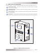
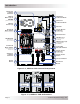
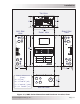
Table Of Contents
- 1.0 Introduction
- 2.0 Installation
- 2.1 Preparation
- 2.2 Location
- 2.3 Conduit Knockouts
- 2.4 Mounting
- 2.5 Wiring the MMP Enclosure – General Requirements
- 2.6 Torque Requirements
- 2.7 Electrical System Wiring Diagrams
- 2.8 DC Wiring
- 2.9 AC Wiring
- 2.10 MMP/Inverter System Grounding
- 2.11 Removing the AC Neutral to Ground Connection
- 2.12 Removing the DC Negative to Ground Busbar
- 2.13 Wiring Accessories
- 2.14 Installation Checklist
- 2.15 Functional Test
- 3.0 Operation
- Appendix A – Optional Equipment and Accessories
- Appendix B – Using the MMP in a Mobile Application
- Appendix C – Warranty and Service
Page 3
© 2013 Magnum Energy, Inc.
Introduction
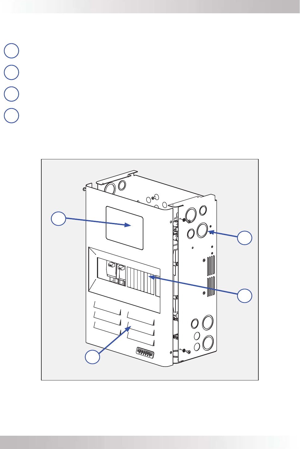
1.2 MMP External Components
As shown in Figure 1-1, the main components found on the outside of the MMP enclosure are:
1
Remote Blank Plate – This plate is removed when an optional ME-RC or ME-ARC
remote control is installed.
2
Conduit Knockouts – Knockouts to allow metal and PVC conduits. For dimensions and
sizes see Figure 2-2.
3
Knockout Panels – Eight 1/2” rectangular knockout panels provided to install additional
DC circuit breakers.
4
Front Cover – The front cover is removed to allow access to the internal components.
Four #10 x 3/8”, T25 Torx drive screws are used to hold the front cover to the enclosure.
Figure 1-1, MMP’s Outside Components
4
2
1
3