
Installation Manual
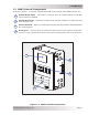
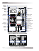
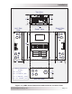
Table Of Contents
- 1.0 Introduction
- 2.0 Installation
- 2.1 Preparation
- 2.2 Location
- 2.3 Conduit Knockouts
- 2.4 Mounting
- 2.5 Wiring the MMP Enclosure – General Requirements
- 2.6 Torque Requirements
- 2.7 Electrical System Wiring Diagrams
- 2.8 DC Wiring
- 2.9 AC Wiring
- 2.10 MMP/Inverter System Grounding
- 2.11 Removing the AC Neutral to Ground Connection
- 2.12 Removing the DC Negative to Ground Busbar
- 2.13 Wiring Accessories
- 2.14 Installation Checklist
- 2.15 Functional Test
- 3.0 Operation
- Appendix A – Optional Equipment and Accessories
- Appendix B – Using the MMP in a Mobile Application
- Appendix C – Warranty and Service

Page 9
© 2013 Magnum Energy, Inc.
Installation
Figure 2-1, MMP Series Simplifi ed Installation Diagram
BATTERY
BANK
AC power to inverter
ON
OFF
ON
OFF
ON
OFF
ON
OFF
ON
OFF
ON
OFF
ON
OFF
ON
OFF
240
VAC
120
VAC
120
VAC
MAIN PANEL
SUB-PANEL
Inverter power
(or pass-thru power)
to Sub-panel
AC
T
RANSFER
SWITCH
GENERATOR POWER
120/240VAC OUTPUT
UTILITY POWER
120/240VAC OUTPUT
ON
OFF
ON
OFF
ON
OFF
ON
OFF
ON
OFF
ON
OFF
ON
OFF
ON
OFF
ON
OFF
ON
OFF
ON
OFF
ON
OFF
ON
OFF
ON
OFF
ON
OFF
30A
30A
MMP
E
NCLOSURE
ON
OFF
63A
ON
OFF
63A
ON
OFF
ON
OFF
63A 0.5A
F
l
u
x
C
a
p
a
c
i
t
o
r
G
e
n
e
r
a
t
o
r
PV PANELS
ME-RC or ME-ARC
Remote Controls
(Magnum Options)
ME-BMK-NS
Battery Monitor
(Magnum Option,
Installs inside)
Magnum Inverter
(Attaches on
top for a
seamless look)
ME-AGS-N
Auto Gen Start Controller
(Magnum Option)
Space for optional
DC circuit breakers
and PV-GFP
PV C
HARGE
CONTROLLER