
Installation Manual
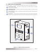
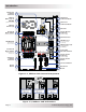
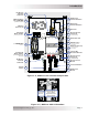
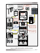
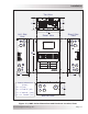
Table Of Contents
- 1.0 Introduction
- 2.0 Installation
- 2.1 Preparation
- 2.2 Location
- 2.3 Conduit Knockouts
- 2.4 Mounting
- 2.5 Wiring the MMP Enclosure – General Requirements
- 2.6 Torque Requirements
- 2.7 Electrical System Wiring Diagrams
- 2.8 DC Wiring
- 2.9 AC Wiring
- 2.10 MMP/Inverter System Grounding
- 2.11 Removing the AC Neutral to Ground Connection
- 2.12 Removing the DC Negative to Ground Busbar
- 2.13 Wiring Accessories
- 2.14 Installation Checklist
- 2.15 Functional Test
- 3.0 Operation
- Appendix A – Optional Equipment and Accessories
- Appendix B – Using the MMP in a Mobile Application
- Appendix C – Warranty and Service
Page 11
© 2013 Magnum Energy, Inc.
Installation
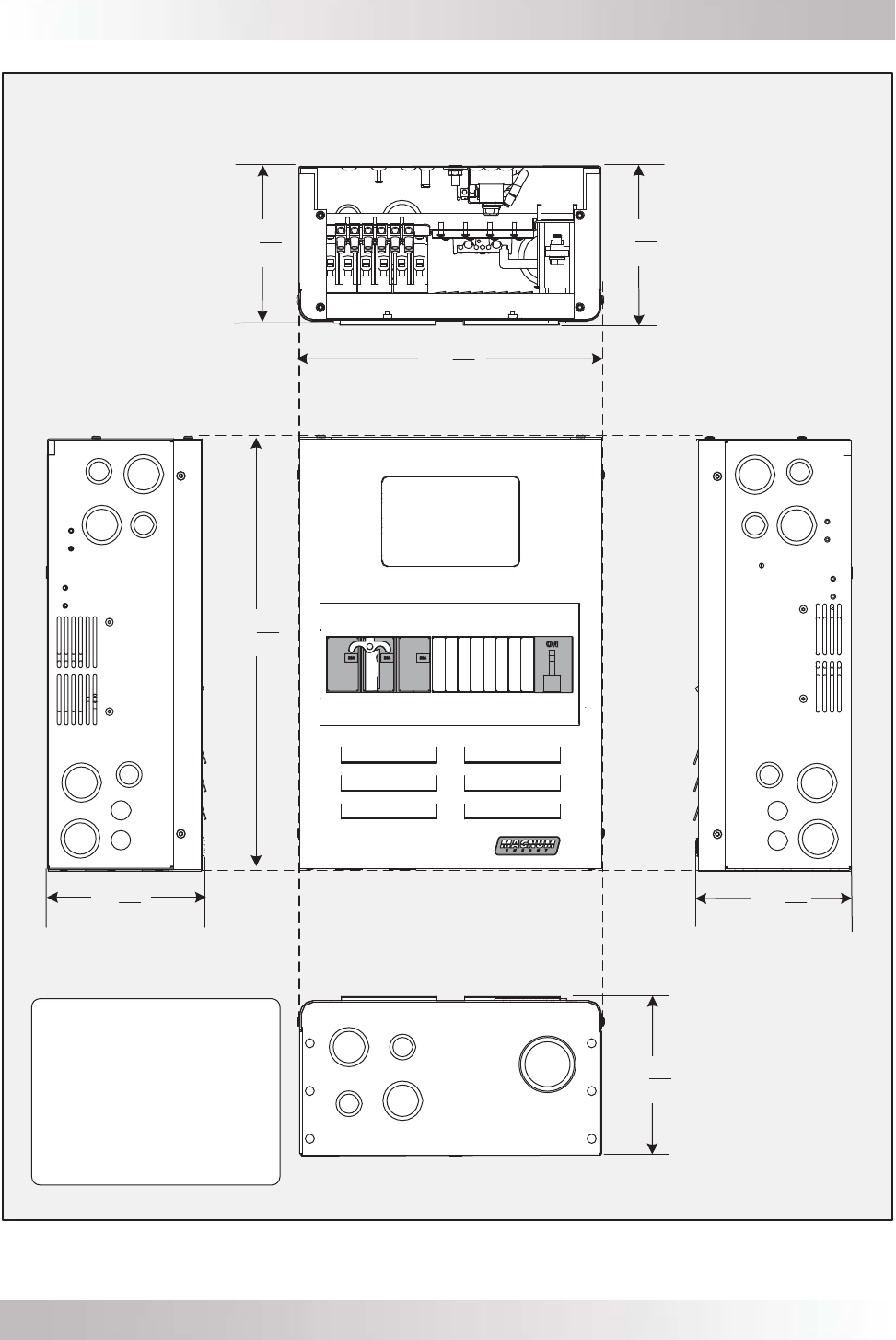
Figure 2-2, MMP Series Dimensions and Knockout Location/Sizes
LEFT SIDE
VIEW
FRONT VIEW
TOP VIEW
BOTTOM VIEW
RIGHT SIDE
V
IEW
CONDUIT KNOCKOUTS
(TOTAL):
A = ½” (x4)
B = ½” and ¾” (x8)
C = 1” and 1¼” (x10)
D = 1 ½” and 2” (x1)
D
C
C
B
B
7
8
12
1
2
6
11
16
6
11
16
6
”
”
”
”
1
16
18
”
C
C
C
C
B
B
B
A
A
11
16
6
”
C
C
C
C
B
B
B
A
A
11
16
6
”