
Installation Manual
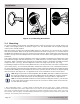
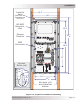
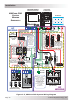
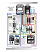
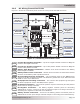
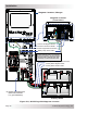
Table Of Contents
- 1.0 Introduction
- 2.0 Installation
- 2.1 Preparation
- 2.2 Location
- 2.3 Conduit Knockouts
- 2.4 Mounting
- 2.5 Wiring the MMP Enclosure – General Requirements
- 2.6 Torque Requirements
- 2.7 Electrical System Wiring Diagrams
- 2.8 DC Wiring
- 2.9 AC Wiring
- 2.10 MMP/Inverter System Grounding
- 2.11 Removing the AC Neutral to Ground Connection
- 2.12 Removing the DC Negative to Ground Busbar
- 2.13 Wiring Accessories
- 2.14 Installation Checklist
- 2.15 Functional Test
- 3.0 Operation
- Appendix A – Optional Equipment and Accessories
- Appendix B – Using the MMP in a Mobile Application
- Appendix C – Warranty and Service
© 2013 Magnum Energy, Inc.Page 20
Installation
DC System Grounding point
[Electrode Conductor
(i.e., ground busbar)]
Magnum Inverter
(front view)
Battery Temp Sensor Cable*
Inverter’s DC Negative Busbar
Inverter’s DC Positive Busbar
Inverter’s Equipment Ground Wire
BTS
BTS
* If the voltage inside the enclosure is
greater than 150 volts (i.e., 120/240
VAC source/inverter), use the provided
extension cable (with 300-volt rated
insulation) to connect the BTS cable
Battery Bank
Battery Bank’s Equipment Ground Wire
Battery Bank’s Negative Cable
Battery Bank’s Positive Cable
Magnum Inverter/Charger
Figure 2-8, DC Wiring with Magnum Inverter