
Installation Manual
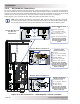

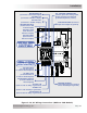

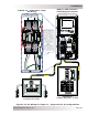
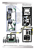
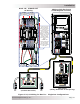
Table Of Contents
- 1.0 Introduction
- 2.0 Installation
- 2.1 Preparation
- 2.2 Location
- 2.3 Conduit Knockouts
- 2.4 Mounting
- 2.5 Wiring the MMP Enclosure – General Requirements
- 2.6 Torque Requirements
- 2.7 Electrical System Wiring Diagrams
- 2.8 DC Wiring
- 2.9 AC Wiring
- 2.10 MMP/Inverter System Grounding
- 2.11 Removing the AC Neutral to Ground Connection
- 2.12 Removing the DC Negative to Ground Busbar
- 2.13 Wiring Accessories
- 2.14 Installation Checklist
- 2.15 Functional Test
- 3.0 Operation
- Appendix A – Optional Equipment and Accessories
- Appendix B – Using the MMP in a Mobile Application
- Appendix C – Warranty and Service
© 2013 Magnum Energy, Inc.Page 30
Installation
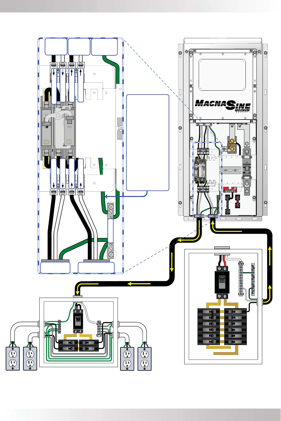
Figure 2-13, AC Wiring for Single In – Single Out (60 A) Confi gurations
GROUND
NEUT IN
HOT 1 IN
HOT 1 OUT
NEUT OUT
NEUT OUT
HOT 1 OUT
HOT 1 IN
NEUT IN
AC OUT
(from
inverter
AC Output)
AC IN
(to
inverter
AC Input)
.AC OUT
(to AC loads)
AC IN
(from grid/gen)
`
`
MMPxxx-60S Enclosure
(with Magnum Inverter)
Main Panel
(Utility/Generator 60A)
ON
OFF
ON
OFF
ON
OFF
ON
OFF
ON
OFF
ON
OFF
ON
OFF
ON
OFF
ON
OFF
ON
OFF
ON
OFF
ON
OFF
ON
OFF
ON
OFF
ON
OFF
SINGLE IN / SINGLE OUT (60A)
AC Wiring
AC GROUND
(to
inverter
AC Input)
Sub-Panel and Outlets
(Inverter AC Loads)
ON
OFF
120
VAC
120
VAC
120
VAC
120
VAC
ON
OFF
ON
OFF
ON
OFF
ON
OFF
If the main panel
has a neutral-to-
ground connection,
unscrew this
‘Ground to Neutral’
wire connection
from the GROUND
busbar.** This will
isolate the neutral
from ground to
prevent multiple
neutral to ground
bonds.
**Note: This
Ground to Neutral
wire has already
been removed in
the inverter diagram
to the right.