
Installation Manual
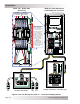
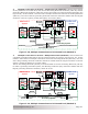
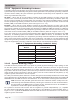
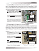
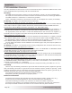
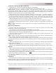
Table Of Contents
- 1.0 Introduction
- 2.0 Installation
- 2.1 Preparation
- 2.2 Location
- 2.3 Conduit Knockouts
- 2.4 Mounting
- 2.5 Wiring the MMP Enclosure – General Requirements
- 2.6 Torque Requirements
- 2.7 Electrical System Wiring Diagrams
- 2.8 DC Wiring
- 2.9 AC Wiring
- 2.10 MMP/Inverter System Grounding
- 2.11 Removing the AC Neutral to Ground Connection
- 2.12 Removing the DC Negative to Ground Busbar
- 2.13 Wiring Accessories
- 2.14 Installation Checklist
- 2.15 Functional Test
- 3.0 Operation
- Appendix A – Optional Equipment and Accessories
- Appendix B – Using the MMP in a Mobile Application
- Appendix C – Warranty and Service
Page 35
© 2013 Magnum Energy, Inc.
Installation
2. Multiple Connections to Ground – Single Electrode (Method 2): When the AC and DC
service panels are near each other, then the AC Grounding Electrode Conductor (GEC–AC) and DC
Grounding Electrode Conductor (GEC–DC) can be connected to a single Grounding Electrode (see
Figure 2-18). In this method—since there are multiple connections to the DC Grounding Electrode
(GEC–DC)—the size of the DC grounding electrode conductor cannot be smaller than the largest
conductor in the DC system (usually the battery-to-inverter cable).
3. Multiple Connections to Ground – Multiple Electrodes (Method 3): This method uses
a separate grounding electrode for the DC system and the AC system (see Figure 2-19). In this
method—since there are multiple connections to the DC Grounding Electrode (GEC–DC)—the size
of the DC grounding electrode conductor cannot be smaller than the largest conductor in the DC
system (usually the battery-to-inverter cable).
The DC Grounding Electrode (GE–DC) must be bonded to the AC Grounding Electrode (GE–AC)
to make a grounding electrode system; this Bonding Conductor (BC) cannot be smaller than the
largest grounding electrode conductor, either AC or DC.
Figure 2-18, Multiple Connections to DC Ground Rod (Method 2)
Figure 2-19, Multiple Connections to DC Ground Rod (Method 3)
DC
S
OURCE
MAIN AC PANEL
HOT 1
NEUT
GND
HOT 2
MMP
AC
S
OURCE
AC and DC sides shared
DC Electrical
System
AC Electrical
System
Grounding System
GND
POS
NEG
GBB
GE
GEC-AC
GBB
MAGNUM
INVERTER
GEC-DC
SBJ
GC-DC
GC-AC
HOT 1
HOT 2
NEUT
BAT
BAT
SBJ
ENCLOSURE
DC
S
OURCE
MAIN AC PANEL
HOT 1
NEUT
GND
HOT 2
ENCLOSURE
AC
S
OURCE
DC side dedicated
AC side dedicated
DC Electrical
System
AC Electrical
System
Grounding System
GND
POS
NEG
GBB
GE
GEC-AC
GE
GBB
MAGNUM
INVERTER
GEC-DC
BC
SBJ
GC-DC
GC-AC
BAT
BAT
HOT 1
HOT 2
NEUT
SBJ
MMP