
Installation Manual
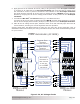
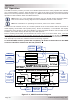

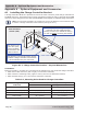


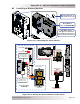
Table Of Contents
- 1.0 Introduction
- 2.0 Installation
- 2.1 Preparation
- 2.2 Location
- 2.3 Conduit Knockouts
- 2.4 Mounting
- 2.5 Wiring the MMP Enclosure – General Requirements
- 2.6 Torque Requirements
- 2.7 Electrical System Wiring Diagrams
- 2.8 DC Wiring
- 2.9 AC Wiring
- 2.10 MMP/Inverter System Grounding
- 2.11 Removing the AC Neutral to Ground Connection
- 2.12 Removing the DC Negative to Ground Busbar
- 2.13 Wiring Accessories
- 2.14 Installation Checklist
- 2.15 Functional Test
- 3.0 Operation
- Appendix A – Optional Equipment and Accessories
- Appendix B – Using the MMP in a Mobile Application
- Appendix C – Warranty and Service
Page 51
© 2013 Magnum Energy, Inc.
Appendix A - Optional Equipment and Accessories
Figure A3-2, Wiring the Sense Module and DC Shunt
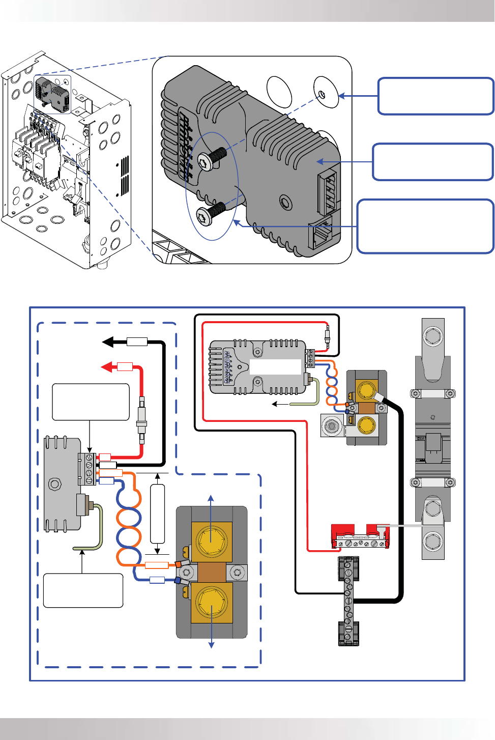
Figure A3-1, Mounting the Sense Module
A3 Installing a Battery Monitor
DC Fuse (2 amps)
To DC
Positive Busbar
To DC
Negative Busbar
orange
blue
black
red
black
red
Twisted-pair cable
4-Port Terminal Block
(can be removed, and
each port accepts
30 to 12 AWG wire).
Communications Cable
(To Network port on
Magnum inverter)
blue
orange
To Battery Bank
To Inverter/Loads
Close-up of wiring
the ME-BMK
Sense Module
(from ME-BMK)
DC Shunt
(in MMP Enclosure)
Battery Positive
Busbar
(in MMP Enclosure)
DC Negative Busbar
(in MMP Enclosure)
To Network Port
MOUNTING DIMPLES W/
#8 SCREW HOLES (X2)
SENSE MODULE
(PART OF ME-BMK-NS)
TWO #8 X 1/2”,
T15 TORX DRIVE SCREWS
(PROVIDED & SCREWED INTO
THE
TWO MOUNTING DIMPLES)