
Installation Manual
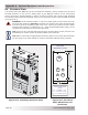
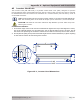

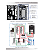
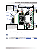


Table Of Contents
- 1.0 Introduction
- 2.0 Installation
- 2.1 Preparation
- 2.2 Location
- 2.3 Conduit Knockouts
- 2.4 Mounting
- 2.5 Wiring the MMP Enclosure – General Requirements
- 2.6 Torque Requirements
- 2.7 Electrical System Wiring Diagrams
- 2.8 DC Wiring
- 2.9 AC Wiring
- 2.10 MMP/Inverter System Grounding
- 2.11 Removing the AC Neutral to Ground Connection
- 2.12 Removing the DC Negative to Ground Busbar
- 2.13 Wiring Accessories
- 2.14 Installation Checklist
- 2.15 Functional Test
- 3.0 Operation
- Appendix A – Optional Equipment and Accessories
- Appendix B – Using the MMP in a Mobile Application
- Appendix C – Warranty and Service
Page 55
© 2013 Magnum Energy, Inc.
Appendix A - Optional Equipment and Accessories
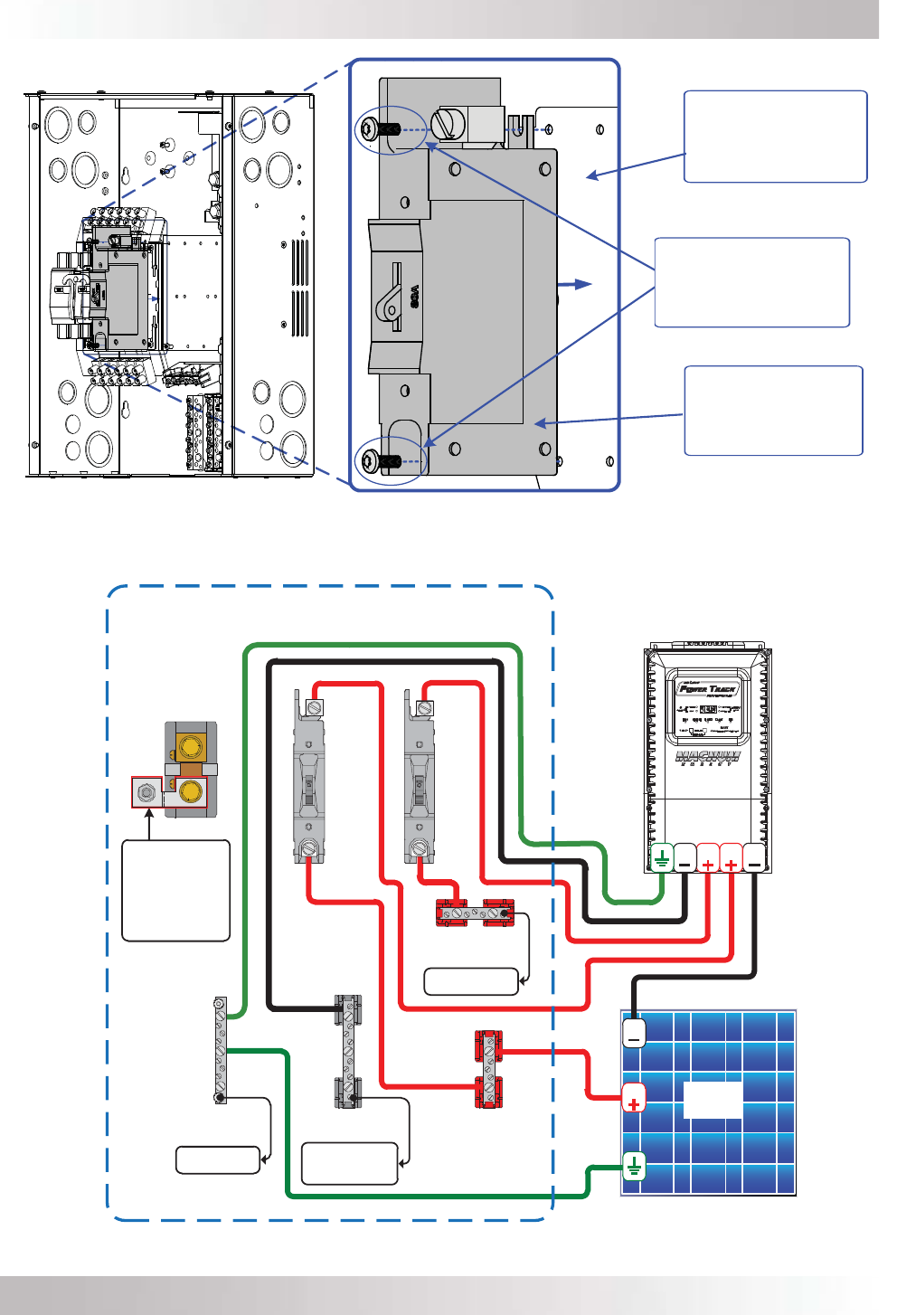
Figure A6-2, Installing Back Panel Mounted DC Breakers
DC NEGATIVE
BUSBAR
BATTERY +
B
REAKER
INSIDE MMP ENCLOSURE
PV CHARGE CONTROLLER
(WITH INTERNAL PV-GFP
PROTECTION)
PV +
B
USBAR
GROUND
BUSBAR
BATTERY +
B
USBAR
TO PRIMARY DC
GROUND SYSTEM
TO BATTERY BANK
NEGATIVE
TERMINAL
(THROUGH DC SHUNT)
TO BATTERY BANK
POSITIVE
TERMINAL
PV +
B
REAKER
PV
PV
P
ANELS
PV
DC S
HUNT
GROUND TO
N
EGATIVE
CONNECTION
(
REMOVE THIS BUSBAR
WHEN PV-GFP IS
INSTALLED TO
PREVENT
MULTIPLE
CONNECTIONS)
PV
PVB
B
SCREW TO BREAKER
MOUNTING PLATE
(REMOVE DIN RAIL)
TWO DC BREAKER
MOUNTING
SCREWS
(USE #8 X 1/2”
LENGTH MINIMUM)
Figure A6-3, Wiring DC Breakers
BACK PANEL
MOUNTED
DC BREAKER
(1” WIDTH)