
Installation Manual


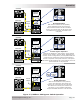

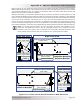


Table Of Contents
- 1.0 Introduction
- 2.0 Installation
- 2.1 Preparation
- 2.2 Location
- 2.3 Conduit Knockouts
- 2.4 Mounting
- 2.5 Wiring the MMP Enclosure – General Requirements
- 2.6 Torque Requirements
- 2.7 Electrical System Wiring Diagrams
- 2.8 DC Wiring
- 2.9 AC Wiring
- 2.10 MMP/Inverter System Grounding
- 2.11 Removing the AC Neutral to Ground Connection
- 2.12 Removing the DC Negative to Ground Busbar
- 2.13 Wiring Accessories
- 2.14 Installation Checklist
- 2.15 Functional Test
- 3.0 Operation
- Appendix A – Optional Equipment and Accessories
- Appendix B – Using the MMP in a Mobile Application
- Appendix C – Warranty and Service
Page 47
© 2013 Magnum Energy, Inc.
Operation
Figure 3-3, MMPxxx-60S Bypass Switch Operation
ON
OFF
ON
OFF
ON
OFF
ON
OFF
ON
OFF
ON
OFF
ON
OFF
ON
OFF
ON
OFF
ON
OFF
ON
OFF
ON
OFF
ON
OFF
ON
OFF
ON
OFF
ON
OFF
ON
OFF
ON
OFF
ON
OFF
ON
OFF
MAGNUM
INVERTER
MAIN PANEL
SUB-PANEL
BYPASS
SWITCH
ON
OFF
ON
OFF
ON
OFF
ON
OFF
ON
OFF
ON
OFF
ON
OFF
ON
OFF
ON
OFF
ON
OFF
ON
OFF
ON
OFF
ON
OFF
ON
OFF
ON
OFF
ON
OFF
ON
OFF
ON
OFF
ON
OFF
ON
OFF
MAGNUM
INVERTER
MAIN PANEL
SUB-PANEL
BYPASS
SWITCH
ON
OFF
ON
OFF
ON
OFF
ON
OFF
ON
OFF
ON
OFF
ON
OFF
ON
OFF
ON
OFF
ON
OFF
ON
OFF
ON
OFF
ON
OFF
ON
OFF
ON
OFF
ON
OFF
ON
OFF
ON
OFF
ON
OFF
ON
OFF
MAGNUM
INVERTER
MAIN PANEL
SUB-PANEL
BYPASS
SWITCH
ON
OFF
ON
OFF
O
N
O
F
F
O
N
O
F
F
ON
OFF
ON
OFF
ON
OFF
ON
OFF
ON
OFF
ON
OFF
ON
OFF
ON
OFF
ON
OFF
ON
OFF
ON
OFF
ON
OFF
ON
OFF
ON
OFF
Normal Operation
With the AC breakers in this position,
power passes through the inverter to
the connected loads. If an AC line failure
occurs, the inverter will use DC power from
the batteries to maintain the loads in the
sub-panel.
Inverter Bypass Operation
With the AC breakers in this position, power passes
directly to the loads in the sub-panel, bypassing the
inverter. In this confi guration, the sub-panel loads will
continue to be powered if inverter maintenance or
service is required. If AC power from the main panel
fails while the AC breakers are in this position, the sub-
panel loads will not be powered.
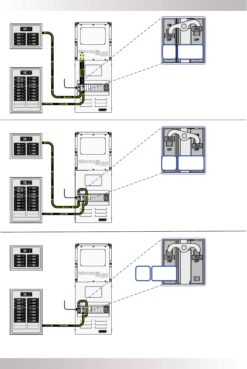
AC OFF Operation
With the AC breakers in this position,
power from both the main panel and
inverter are removed from the sub-panel.
This allows the inverter, the loads in the
sub-panel, or any installed equipment
beyond the MMP enclosure to be serviced.
INV INPUT &
INV OUTPUT
= ON
INV
BYPASS
= OFF
INV INPUT &
INV OUTPUT
= OFF
INV
BYPASS
= ON
INV INPUT &
INV OUTPUT
= OFF
INV
BYPASS
= OFF