MS Series Pure Sine Wave Inverter / Charger Operators Manual
IMPORTANT SAFETY INSTRUCTIONS This manual contains important safety instructions that must me followed during the installation and operation of this product. To reduce the risk of electrical shock, fire, or other safety hazard, the following safety symbols have been placed throughout this manual to indicate dangerous and important safety instructions. WARNING - Indicates a dangerous voltage or condition exists.
IMPORTANT BATTERY SAFETY INSTRUCTIONS Wear eye protection such as safety glasses when working with batteries. Remove all jewelry such as rings, watches, bracelets, etc., when installing or performing maintenance on the inverter. Never work alone. Always have someone near you when working around batteries. Use proper lifting techniques when working with batteries. Never use old or untested batteries. Check each battery's label for age, type and date code to ensure all batteries are identical.
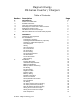
Magnum Energy MS Series Inverter / Chargers Table of Contents Section Description 2. 1. 2.
Table of Contents, continued Section Description 2. 4. Installation, continued Options Battery Temperature Sensor Installation and Wiring Remote Control Installation and Wiring AGS Module Smart Shunt Stacking Cable Kit Start-up and Test Connecting the Batteries to the Inverter Final Inspection and Power-up Configuring the Inverter 25 25 25 25 25 25 26 26 26 27 3. 1.
1. INTRODUCTION 1. Features and Benefits Congratulations on your purchase of the MS Series inverter/charger from Magnum Energy. The MS Series is a pure sine wave inverter designed especially for rugged mobile applications. Powerful, yet simple to use, the Magnum Energy inverter will provide you with years of trouble-free performance so you can enjoy the all of the comforts you have come to expect from your RV, boat, or truck, all backed by our limited 3 year (36-month warranty).
1. INTRODUCTION 3. How an Inverter/Charger Works An inverter takes direct current (DC) from your batteries and turns it into alternating current (AC), exactly like you use at home. It also takes alternating current (when connected to shore power) and transforms it into direct current to recharge your batteries.
1. INTRODUCTION 4. Advantages of a Pure Sine Wave Inverter Todays inverters come in two basic output waveforms: modified sine (which is actually a modified square wave) and pure sine wave. Modified sine wave inverters approximate a pure sine waveform and will run most appliances and electronics without any problems. These inverters are less expensive and, therefore, offer a viable alternative to more expensive pure sine inverters.
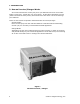
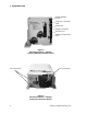
1. INTRODUCTION Power ON/OFF Switch Charging / Inverting LED Stack Port Magnum Net Port Remote Port Battery Temp Sensor Port Figure 2 MS Series Inverter / Charger Switch, LED and Connection Ports DC Connections AC Connections Figure 3 MS Series Inverter / Charger Electrical Connection Points 4 2004 - Magnum Energy, Inc.
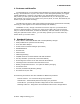
1. INTRODUCTION 6. The MS Series Inverter/Charger The MS Series inverter/charger is designed to allow easy access to wiring, circuit breakers, controls and LED status indicator. Its die cast baseplate with one piece aluminum cover ensures maximum durability with minimum weight, as well as cooler more efficient operation. The inverter is equipped with the following features: ON / OFF Switch - used to manually switch the inverter ON and OFF.
1. INTRODUCTION 7. MS Series Neutral-to-Ground Safety System All MS Series inverters employ an internal, neutral-to-ground safety feature, in accordance with applicable electrical codes for use in mobile applications. This design prevents an electrical shock hazard between the vehicles neutral and the shore powers neutral (when connecting the inverter to shore power).
2. INSTALLATION 1. Unpacking and Inspection Carefully remove the MS Series inverter from its shipping container and inspect all contents. If items appear to be missing or damaged, contact Magnum Energy at (425) 353-8833 or your authorized Magnum Energy dealer. If at all possible, retain the shipping container in the event the unit ever needs to be returned for factory service. ATTENTION: Electrostatic Sensitive Devices. Observe precautions for handling. 2.
2. INSTALLATION 2. Pre-Installation, continued Hardware / Materials Required Conduit, strain-reliefs and appropriate fittings 1/4" mounting bolts and lock washers Electrical tape Wire ties Tools Required Misc screw drivers Drill and drill bits Level Level Pliers Pencil or Marker 1/2" wrench Wire strippers Multimeter Wiring Pre-plan the wire and conduit runs. For maximum safety, run both AC and DC wires/cabling in (separate) conduit.
2. INSTALLATION 2. Pre-Installation, continued Torque Requirements Torque all AC wiring connections to 16 inch pounds. Torque DC cable connections to 10-12 foot pounds. AC Main Panel If the installation will be powering a wide-range of appliances throughout the vehicle, an AC main panel is often recommended. This is similar in appearance and function as your homes circuit breaker panel, providing an additional level of control and protection for the various circuits.
2. INSTALLATION 3. Installation NOTE: Read all instructions and cautionary markings located at the beginning of this manual and in the pre-installation section, before installing the inverter and batteries. CAUTION: Do not mount the inverter or the batteries near the vehicles gasoline or propane fuel tanks. Provide adequate clearance and ventilation to the inverter Mount the inverter only on a noncombustible surfaces. Maximum abient temperature MUST NOT exceed 113 °F (45 °C).
2. INSTALLATION 3. Installation, continued Battery Installation NOTE: To ensure the best performance from your inverter system, do not use old or untested batteries. Batteries must be of the same size, type, rating and age. NOTE: For optimum performance, Magnum Energy recommends using AGM (absorbed glass mat) batteries such as LifelineTM brand batteries. NOTE: If using Flooded Lead Acid batteries, they must be mounted upright. CAUTION: Install batteries in a well ventilated area.
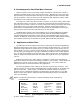
2. INSTALLATION 3. Installation, continued Battery Cables and Sizing Select the correct battery cables for the installation from the table. It is important to use the correct cable to achieve maximum efficiency from the system and reduce fire hazards associated with overheated cables. Undersized cables can also lower the inverters peak output voltage as well as reduce its surge power capability. Long cable runs also reduce efficiency due to resistance in the cable.
2. INSTALLATION 3. Installation, continued Battery Wiring WARNING: During the installation and wiring process, cover exposed battery cable ends with electrical tape to prevent shorting the cables. NOTE: DO NOT connect the positive cable to the inverter at this time. Depending upon the type of battery you use in the installation (6 or 12 VDC), the batteries must be wired in series, parallel or series/parallel to provide 12 VDC.
2.
2. INSTALLATION 3. Installation, continued Series Connection (four 6 VDC batteries to create a 24 VDC bank) A series connection combines overall battery voltage by the number of batteries in the string. Even though there are multiple batteries, the capacity remains the same. In the example at the left (Figure 8), four 6 VDC, 100 AHr batteries are combined into a single string resulting in a 24 VDC, 200 AHr bank.
2. INSTALLATION In-line fuse ~ + + + + 12 VDC 12 VDC 12 VDC 12 VDC - - - - + > TO 12 VDC INVERTER - > Figure 11 Parallel Battery Wiring - Fuse Placement In-line fuse ~ + 6 VDC - + 6 VDC - + 6 VDC - + 6 VDC + > TO 24 VDC INVERTER - > Figure 12 Series Battery Wiring - Fuse Placement In-line fuse ~ + 6 VDC - + 6 VDC - + 6 VDC - + 6 VDC + TO 12 VDC INVERTER - Figure 13 Series/Parallel Battery Wiring - Fuse Placement 16 > > 2004 - Magnum Energy, Inc.
2. INSTALLATION 3. Installation, continued DC Fuse Block A fuse or circuit breaker must be located within 18 inches of the battery to protect the DC wiring system. The device must be rated to match the size of the cable, but can be rounded up to the next larger size (i.e., a cable rated at 150 amps can accept a 175 amp fuse) as necessary. Mount the fuse block (or circuit breaker assembly) as near as practical to the batteries.
2. INSTALLATION Positive Battery Terminal Negative Battery Terminal AC Output Cable Clamp AC Input Cable Clamp DC Chassis Ground Figure 14 MS Series Inverter / Charger - AC Wiring MS Series Nameplate Label AC Access Cover AC Input Circuit Breaker AC Output 2 Circuit Breaker (on dual output models only) AC Output 1 Circuit Breaker (on dual output models only) Figure 15 MS Series Inverter / Charger - AC Wiring (Access Panel) 18 2004 - Magnum Energy, Inc.
2. INSTALLATION 3. Installation, continued AC Wiring WARNING: De-energize all sources of power including batteries (DC), shore power (AC), and AC generator (if applicable). AC wiring must be performed by a qualified person or licensed electrician. DO NOT connect the inverters output to an AC power source. WARNING: Risk of electric shock.
2. INSTALLATION Figure 16 MS Series Inverter / Charger - AC Wiring Diagram (located on back of cover plate) HOT 1 OUT HOT 2 OUT NEUT OUT HOT 2 IN HOT 1 IN NEUT IN AC Ground Figure 17 MS Series Inverter / Charger - AC Terminal Block 20 2004 - Magnum Energy, Inc.
2. INSTALLATION 3. Installation, continued Wiring the Inverter AC Input (refer to diagrams on the following pages) Remove the chassis AC access cover to access the internal terminal block. Route the cable and conduit from the main panel, approved bypass selector switch or main AC panel to the inverters AC INPUT conduit clamp. Tighten the clamp securely on the conduit. Always leave a little extra slack in the wiring.
2.
2.
2. INSTALLATION Stack Port Magnum Net Port Remote Port Battery Temp Sensor Port Figure 21 MS Series Inverter / Charger - Option Connection Ports 24 2004 - Magnum Energy, Inc.
2. INSTALLATION 4. Options AGS Module The Auto Gen Start (AGS) is designed to automatically start your coach generator based on low battery condition or the inside temperature of the coach. These features allow you to enjoy a day away golfing, touring or just sight seeing, all the while knowing your coach will stay cool and comfortable and your batteries will stay charged. There's nothing better than returning to a nice cool comfortable coach with charged batteries while dry camping in hot weather.
2. INSTALLATION 5. Start-up and Test Connecting the Batteries to the Inverter After all electrical connections have been completed, connect the batteries to the inverter to begin the start-up process. CAUTION: Verify correct battery voltage and polarity before connecting the cables to the inverter. Replace the fuse or (close the breaker) at the DC disconnect. Remove the electrical tape from the cable lugs and verify 12 VDC at the cable connectors using a multimeter.
2. INSTALLATION 5. Start-up and Test, continued Configuring the Inverter The MS Series inverter/charger must be configured for Low Battery Cutoff (LBCO), Shore Power Current, Charger Amps, Battery Size and Battery Type. These operational parameters must be configured using the optional remote control.
3. OPERATION Charging / Inverting LED Figure 22 MS Series Inverter / Charger - LED Indicator 28 2004 - Magnum Energy, Inc.
3. OPERATION 1. Operating the Inverter The MS Series inverter/charger has two modes of operation: INVERTER (providing power to your appliances from the batteries) and AC (running from shore power or a generator). Whenever the inverter is in AC mode, it passes power directly to your appliances as well as recharges the batteries using a 3-stage battery charger (Bulk, Absorption and Float).
3. OPERATION LED Figure 23 MS Series Inverter / Charger - Fault Conditions Fault LED Figure 24 Optional Remote Control - Fault Conditions 30 2004 - Magnum Energy, Inc.
3. OPERATION 1. Operating the Inverter, continued Fault or Alarm Conditions The inverter monitors the AC Shore Power, the batteries and itself. Whenever a condition occurs that is outside the normal operating parameters, the inverter will take the necessary steps to protect your appliances, batteries or itself from damage.
4. TROUBLESHOOTING this page left blank 32 2004 - Magnum Energy, Inc.
4. TROUBLESHOOTING 1. Basic Troubleshooting The MS Series inverter/ charger is a fairly simple device to troubleshoot. There are only two active circuits (AC and DC) as well as a charging circuit. The following chart is designed to help you quickly pinpoint the most common inverter failures. WARNING: De-energize all sources of power including batteries (DC), shore power (AC), and AC generator (as applicable). Symptom Possible Cause Recommended Solution No output power. Inverter LED is OFF.
5. PREVENTIVE MAINTENANCE 1. Recommended Inverter and Battery Care The MS Series inverter/ charger is designed to provide you with years of troublefree service. Even though there are no user-serviceable parts, it is recommended that every 6 months you perform the following maintenance steps to ensure optimum performance and extend the life of your batteries. WARNING: Prior to performing these checks, switch both the AC and DC circuits OFF.
6. SPECIFICATIONS MS Series Specifications MS2012 MS2812 MS3624 12.6 VDC 120 VAC 60 Hz ± 0.04% > 5% 60 37 3700 3450 3100 2400 2000 VA 190 ADC 89% 16 msecs 0.3 ADC 2 ADC Pure Sine Wave 12.6 VDC 120 VAC 60 Hz ± 0.04% > 5% 70 40 3900 3800 3200 3000 2800 VA 267 ADC 88% 16 msecs 0.3 ADC 2 ADC Pure Sine Wave 25.2 VDC 120 VAC 60 Hz ± 0.04% > 5% 100 60 6500 5500 5000 4000 3600 VA 336 ADC 87% 16 msecs 0.3 ADC 2 ADC Pure Sine Wave 100 ADC 85% 0.98 15 125 ADC 85% 0.98 18 100 ADC 85% 0.
7. WARRANTY 36 Month Limited Warranty Magnum Energy, Inc., warrants the MS Series Inverter / Charger to be free from defects in material and workmanship that result in product failure during normal usage, according to the following terms and conditions: 1. The limited warranty for the product extends for 36 months beginning from the product's original date of purchase. 2. The limited warranty extends to the original purchaser of the product and is not assignable or transferable to any subsequent purchaser.
1111 80th Street SW - Suite 250 Everett, WA 98203 p: 425.353.8833 f: 425.