
Installation Manual


© 2009 Magnum Energy IncPage 12
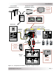
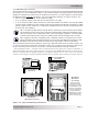
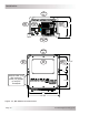
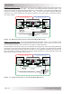
Figure 2 - 4 , Grounding System for M S- PAE Se rie s
2 .2 Gr ounding I nverters
The MS-PAE Series inverters use two separate electrical systems (AC and DC power), therefore
each electrical system is required to be properly connected to a permanent, common “ground” or
“earth” reference. An inverter system that is properly grounded limits the risk of electrical shock,
reduces radio frequency noise and minimizes excessive surge voltages induced by lightning. To
understand how the conductors in the electrical circuit will be connected to the system ground,
the following terms should be understood (also refer to fi gure 2-4):
Grounded Conductor ( GC) : The wire/cable in the electrical system that normally carries current
(usually the AC neutral and/or the DC negative); and is intentionally connected or “bonded” to
the ground system. This wire or the ends of this wire should be colored white or gray.
Equipment Grounding Conductor ( EGC) : A wire/cable that does not normally carry current and
is used to connect the exposed metal parts of equipment - that might be accidentally energized
- to the grounding electrode system or the grounded conductor. This wire or the ends of this
wire should be green or green with a yellow stripe; or this wire can be bare copper.
Grounding Electrode Conductor ( GEC) : The wire/cable that does not normally carry current and
connects the grounded conductor and/or the equipment grounding conductor to the grounding
electrode at the service equipment.
Grounding Electrode ( GE) : A ground rod or conducting element that establishes an electrical
connection to the earth or common ground reference.
System bonding jumper (SBJ) The connection between the grounded circuit conductor in the
electrical system and the equipment grounding conductor at a separately derived system.
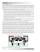
There are two types of grounding - equipment grounding and system grounding.
The exposed metal parts of the equipment in the system usually don’t carry electricity. However,
if the exposed metal becomes electrifi ed by a live wire, a person touching this live part could
complete the electrical circuit and receive a shock. Equipment grounding prevents shock by con-
necting all the exposed metal parts of equipment (via Equipment Grounding Conductors - EGC)
together at a common ground point (Ground Bus-Bar - GBB). This common ground point - installed
in the service disconnect panel for each electrical system (AC and DC) - is then connected (via
Grounding Electrode Conductor - GEC) to the common ground reference, such as a ground rod
(Grounding Electrode - GE). This connection to earth is made at only one point in each electrical
system; otherwise, parallel paths will exist for the currents to fl ow. These parallel current paths
would represent a safety hazard and are not allowed in installations wired per the NEC/CEC.
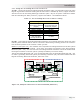
System grounding takes one of the current-carrying conductors (Grounded Conductor - GC) and
attaches it to the common ground point (Ground Bus-Bar - GBB) usually by a System Bonding
Jumper (SBJ) in each electrical service disconnect panel. On the DC side that is the negative con-
ductor; on the AC side it’s the neutral conductor. The closer the grounding connection is to the
source, the better the protection from surges due to lightning.
•
•
•
•
•
AC
DC Service
Panel
AC Service
Panel
DC Electrical SystemAC Electrical System
Neutral
Positive
Negative
DC
Grounding
System
Negative
SBJ
GC
GE
GEC-AC
EGC
AC Ground DC Ground
SBJ
EGC
GC
Neutral
Hot
GEC-DC
GE
GE
GBB GBB
Grounding Electrode
(AC and DC sides shared)
Grounding Electrode
(DC side dedicated)
Grounding Electrode
(AC side dedicated)
or
or
MS-PAE Series Inverter/Charger
I nst alla t ion