
Installation Manual


© 2009 Magnum Energy IncPage 14
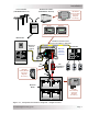
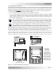
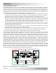
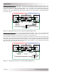
Method 2 (see fi gure 2-6): When the AC and DC service panels are near each other, then the AC
Grounding Electrode Conductor (GEC – AC) and DC Grounding Electrode Conductor (GEC – DC)
can be connected to a single Grounding Electrode. In this method - since there are multiple con-
nections to the DC Grounding Electrode (GEC – DC) - the size of the DC Grounding Electrode
Conductor can not be smaller than the largest conductor in the DC system (usually the battery-
to-inverter cable).
Figure 2 - 6 , M ult iple Conne ct ions t o DC Gr ound Rod ( M ethod 2 )
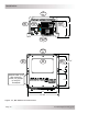
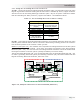
Figure 2 - 7 , Single Connection t o DC Grou nd Rod ( M et hod 3 )
Method 3 (see fi gure 2-7): The AC Grounding Electrode Conductor (GEC – AC) is bonded to the
DC ground point and the DC Grounding Electrode Conductor (GEC – DC) is the only connect ion to
the Grounding Electrode, which must be a rod, pipe, or plate electrode.
In this method, since there is only one connection to the ground rod, the DC Grounding Electrode
Conductor is not required to be larger than #6 AWG (13 mm
2
) copper. The reasoning for allowing
this smaller grounding electrode conductor is that it is only required to stabilize the system volt-
age with respect to earth and the other properly-sized conductors in each electrical system will
safely carry any fault currents if they occur.
I nst alla t ion
AC
DC Service
Panel
AC Service
Panel
DC Electrical SystemAC Electrical System
Neutral
Positive
Negative
DC
Grounding
System
Negative
SBJ
GC
GE
GEC-AC
EGC - AC
AC Ground DC Ground
SBJ
EGC - DC
GC
Neutral
Hot
GEC-DC
GBB GBB
Grounding Electrode
(AC and DC sides shared)
MS-PAE Series Inverter/Charger
AC
DC Service
Panel
AC Service
Panel
DC Electrical SystemAC Electrical System
Neutral
Positive
Negative
DC
Grounding
System
Negative
SBJ
GC
GEC-AC
EGC - AC
AC Ground DC Ground
SBJ
EGC - DC
GC
Neutral
Hot
GEC-DC
GE
GBB GBB
Grounding Electrode
(DC side dedicated)
MS-PAE Series Inverter/Charger