
Installation Manual

© 2009 Magnum Energy IncPage 20
2 .3 .4 W iring t h e Battery Bank
W ARN I NG: Lethal currents will be present if the positive and negative cables attached
to the battery bank touch each other. During the installation and wiring process, en-
sure the cable ends are insulated or covered to prevent touching/shorting the cables.
I nfo: DO NOT connect the DC wires from the battery bank to the inverter until 1) all
DC and AC wiring is complete, 2) the correct DC and AC overcurrent protection has
been installed and 3) the correct DC voltage and polarity have been verifi ed.
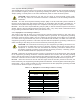
I nfo: For the MS-PAE Series inverter/charger to perform optimally, a minimum battery
bank of 200 AH is recommended for moderate loads (<1000W) and greater than 400
AH for heavy loads (≥1000W).
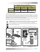
Depending upon the type of batteries you use in the installation (6 or 12 VDC), the batteries must
be wired in series, parallel or series-parallel to provide the correct voltage (see Appendix C - Bat-
tery Wiring, for guidance on wiring batteries together). The interconnecting DC wires must be sized
and rated exactly the same as those that are used between the battery bank and the inverter.
Place the batteries as close as practical to the inverter, preferably in an insulated and ventilated
enclosure. Allow adequate space above the batteries to access the terminals and vent caps (as
applicable). Also allow at least 1” of space between the batteries to provide good air fl ow. DO NOT
mount the batteries directly under the inverter.
I nfo: To ensure the best performance from your inverter system, batteries should be of
the same size, type, rating and age. Do not use old or untested batteries.
CAUTI ON : Install batteries in a well ventilated area. Batteries can produce explosive
gasses. For compartment/enclosure installations, always vent batteries to the outside.
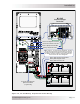
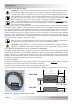
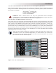
2 .3 .5 Bat t ery Tem pera t ure Se nsor I nstalla t ion a nd W ir ing
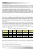
The Battery Temperature Sensor (shown in fi gure 2-11) provides the inverter with precise battery
temperature information to automatically adjusts the battery charger’s BULK, ABSORB and FLOAT
voltage setpoints This allows the batteries to be correctly charged under extreme temperature
changes. If the temperature sensor is NOT installed and if the batteries are subjected to large
temperature changes, the battery life may be shortened.
To install t he BTS:
Attach the ring terminal end of the Battery Temperature Sensor to the negative battery terminal;
see fi gure 2-9 for proper connection to the battery terminal.
Route the sensor’s cable to the inverter following existing wire runs.
Connect the RJ11 connector end of the BTS cable to the BTS port (yellow label) on the inverter.
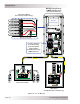
FRONT VIEW
SIDE VIEW
~2"
~1"
~½”
0.375" diameter
Cable
~¾”
Figure 2 - 1 1 , Ba t t e ry Te m pe ratur e Sensor
I nst alla t ion
FRONT VIEW
SIDE VIEW