
Owners Manual
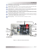
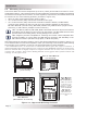
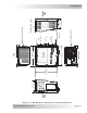
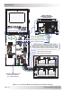
Table Of Contents
- 1.0 Introduction
- 2.0 Installation
- 3.0 Operation
- 4.0 Maintenance and Troubleshooting
- Appendix A – Specifi cations and Optional Equipment
- Appendix B - Battery Information
- Appendix C – Power Consumption and Output Waveforms
- Appendix D – Inverter/Charger Terminology
- Appendix E – Warranty and Service Information

Page 4
© 2013 Magnum Energy, Inc.
I ntr oduct ion
Figure 1 - 2 , Elect r ica l Conne ct ion Point s
9
10
8
7
12
11
Positive (+)
DC Te rm inal
N ega t ive (-)
DC Te rm inal
Mount ing
Flange
DC Equipm ent
Groun d Te rm inal
AC Entry/ Exit
Conne ct ions
I nt a k e Air Ve nts
(and on right side)
7
DC Equipm ent Gr ound Te rm inal – this connection is used to tie the exposed chassis
of the inverter to the DC grounding system. This terminal accepts CU/AL conductors from
2.1 to 33.6 mm
2
(#14 to #2 AWG).
8
AC Entry/ Exit Con nect ions – two 3/4” knockouts provided with cable-clamp
strain
reliefs to accommodate and secure the AC input and output fi eld wiring.
9
I nt ake Air Ven t s – ventilation openings to pull in air to help keep the inverter cool for
peak performance. The intake air vents are located on the front side and at the front on
the right side; see Figure 2-3 for the locations of the air vents.
1 0
Positive DC Te rm inal ( red) – provides a 360 degree connection point for the positive
(+) cable from the battery bank; consists of a 5/16-18 x 5/8” bolt with a Kep or Flange
nut that holds the battery cable to the DC terminal.
1 1
N ega t ive DC Term inal ( bla ck) – provides a 360 degree connection point for the negative
(-) cable from the battery bank; consists of a 5/16-18 x 5/8” bolt with a Kep or Flange
nut that holds the battery cable to the DC terminal.
1 2
Mount ing Flange – used to secure the inverter to a shelf or to a wall.