
Owners Manual
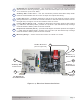
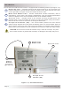
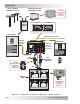
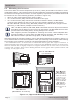
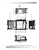
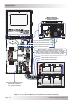
Table Of Contents
- 1.0 Introduction
- 2.0 Installation
- 3.0 Operation
- 4.0 Maintenance and Troubleshooting
- Appendix A – Specifi cations and Optional Equipment
- Appendix B - Battery Information
- Appendix C – Power Consumption and Output Waveforms
- Appendix D – Inverter/Charger Terminology
- Appendix E – Warranty and Service Information

© 2013 Magnum Energy, Inc.Page 11
I nst alla t ion
2 .3 W ir ing t he I nve rt e r – Ge ner al Re quirem ent s
This section describes the requirements and recommendations for wiring the MS-PE Series inverter/
charger. Before wiring the MS-PE Series inverter/charger, read all instructions.
All w iring should m eet a ll loca l codes a nd indust r y st a nda rds, a nd be pe rfor m ed by
qualifi ed personnel su ch a s a license d e lect r ician.
I nfo: This document uses the term “ground”, or “grounding”; the European equivalent
is “earth”, or “earthing”. Refer to Appendix A-3 for equivalent AC/DC wiring terminology.
Inverter/charger systems involve power from multiple sources (e.g., inverter, generator, utility,
batteries, solar arrays, etc.,) which makes the wiring more hazardous and challenging.
The input and output AC and DC circuits are isolated from the inverter chassis. The inverter system
grounding is the responsibility of the installer in accordance with local codes and standard safety
practices.
W ARN I NG: Ensure all sources of DC power (e.g., batteries, solar, wind, or hydro)
and AC power (utility power or AC generator) are de-energized (i.e., breakers opened,
fuses removed) before proceeding—to prevent accidental shock.
2 .3 .1 Prot ect in g W ire – Conduit Box or I nverter Enclosure
The AC and DC wires into and out of the inverter must be protected as required by code.
This can be done by using jacketed wires or by feeding the wires through conduit. To this
end, Magnum offers DC conduit boxes (ME-CB or MPX-CB) and single (MMP-E Series) or
multiple (MP-E Series) inverter enclosures. The enclosures include the necessary AC and
DC inverter breakers that allow both the AC and DC conduit to be connected to the inverter.
I nfo: Remove the strain reliefs and replace with 3/4” grommets if using the ME-CB or
MPX-CB conduit boxes, MS-CEFB fi lter box, or either Magnum enclosure system.
2 .3 .2 W iring Requ ir e m ents
• All conductors that are at risk for physical damage must be protected by conduit, tape, or
placed in a raceway.
• Always check for existing electrical, plumbing, or other areas of potential damage prior to
making cuts in structural surfaces or walls.
• Do not mix AC and DC wiring in the same conduit or panel unless specifi cally approved/
designed for both AC and DC wiring. Where DC wiring must cross AC or vice-versa, try to
make the wires at the crossing point perpendicular (90 degrees) to one another.
• Both AC and DC overcurrent protection m ust be provided as part of the installation.
• The inverter requires a reliable negative and ground return path directly to the battery.
• Use only copper wires with a minimum temperature rating of 75°C.
2 .3 .3 W ire Rout ing
Before connecting any wires, determine all wire routes to and from the inverter. Typical routing
scenarios:
• AC input wiring from the main AC panel to the inverter
• AC input wiring from a generator (optional) to the inverter
• DC input wiring from the batteries to the inverter
• AC output wiring from the inverter to the AC sub-panel or to dedicated circuits
• Battery Temperature Sensor cable from the inverter to the batteries
• Remote control cable (optional) to the inverter
• Ground wiring to and from the inverter
2 .3 .4 Torque Requirem ents
• Torque all AC wiring connections to 1.8 N-m (16 in lbf). Torque DC cable connections from
13.6 to 16.3 N-m (10 to 12 ft lbf).