
Owners Manual
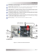
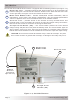
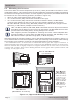
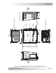
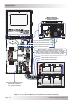
Table Of Contents
- 1.0 Introduction
- 2.0 Installation
- 3.0 Operation
- 4.0 Maintenance and Troubleshooting
- Appendix A – Specifi cations and Optional Equipment
- Appendix B - Battery Information
- Appendix C – Power Consumption and Output Waveforms
- Appendix D – Inverter/Charger Terminology
- Appendix E – Warranty and Service Information

Page 12
© 2013 Magnum Energy, Inc.
I nst alla t ion
2 .4 D C W iring
This section describes the inverter’s required DC wire sizes, the recommended disconnect/
overcurrent protection, and how to make the DC connections to the inverter and the battery bank.
Refer to Figure 2-4 when connecting the DC wires.
W ARN I NG: Even though DC voltage is “low voltage”, signifi cant hazards may be
present, particularly from short circuits of the battery system.
CAUTI ON : The inverter is NOT reverse polarity protected—which means that if the
negative and positive battery voltage is connected backwards to the inverter, the
inverter will likely be damaged. You should verify the correct voltage polarity using a
voltmeter BEFORE connecting the DC wires.
CAUTI ON : Before wiring the DC cables, review the safety information at the beginning
of this manual and the instructions below to ensure a safe and long-lived system.
I nfo: DO NOT connect the battery cables to the inverter until all wiring is complete and
the correct DC voltage and polarity have been verifi ed.
• When the inverter is installed in a photovoltaic system, standard safety practices require that
the DC circuit conductors and overcurrent devices to the inverter be sized to carry not less
than 125% of the inverter’s maximum current rating.
• The DC positive and negative cables connected to the inverter from the battery bank should
be tied together with wire ties or electrical tape approximately every 15.2 cm (6”). This
helps improve the surge capability and reduces the effects of inductance, which improves the
inverter waveform and reduces the wear of the inverter’s fi lter capacitors.
• Use crimped and sealed copper ring terminal lugs to connect the DC wires to the inverter’s
DC terminals. (We use 5/16” terminal lugs here in U.S., determine the European equivalent.)
• The battery bank voltage m ust match the DC voltage required by the inverter (i.e., 24-volt
battery bank for a 24-volt inverter), or the inverter may be damaged.
• To ensure the maximum performance from the inverter, all connections from the battery bank
to the inverter should be minimized. The exceptions are the DC overcurrent disconnect in the
positive line and a shunt in the negative line. Any other additional connection will contribute
to additional voltage drops, and these extra connection points may loosen during use.
• All wiring to the battery terminals should be checked periodically (once a month) for proper
tightness. The torque requirement for the DC terminals is between 13.6 to 16.3 N-m (10 to 12
ft lbf). If you do not have a torque wrench, ensure all DC terminals are tight and cannot move.
• Be aware that overtightening or misthreading the nuts on the DC terminals can cause the
bolts to strip and snap/break off.
• Make sure cables have a smooth bend radius and do not become kinked. Place long cable runs
in conduit and follow existing wire runs where possible.
• A brief spark or arc may occur when connecting the battery cables to the inverter DC terminals;
this is normal and due to the inverter’s internal capacitors being charged.
• Color code the DC cables/wires with colored tape or heat shrink tubing: BROWN for positive (+);
BLUE for negative (-); and GREEN (or GREEN w/YELLOW stripe) for DC ground to avoid polarity
problems. Refer to Table A-2 (in Appendix A-3) for a list of equivalent DC wiring color codes
for Europe and U.S./Canada.