
Owners Manual
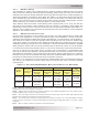
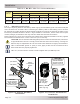

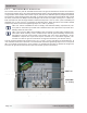
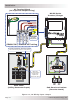
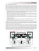
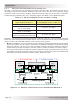
Table Of Contents
- 1.0 Introduction
- 2.0 Installation
- 3.0 Operation
- 4.0 Maintenance and Troubleshooting
- Appendix A – Specifi cations and Optional Equipment
- Appendix B - Battery Information
- Appendix C – Power Consumption and Output Waveforms
- Appendix D – Inverter/Charger Terminology
- Appendix E – Warranty and Service Information

Page 16
© 2013 Magnum Energy, Inc.
I nst alla t ion
2 .4 .4 W iring t he Ba t t ery Bank
W ARN I NG: Lethal currents will be present if the positive and negative cables attached
to the battery bank touch each other. During the installation and wiring process, ensure
the cable ends are insulated or covered to prevent touching/shorting the cables.
I nfo: DO NOT connect the DC wires from the battery bank to the inverter until: 1) all
DC and AC wiring are completed, 2) the correct DC and AC overcurrent protection have
been installed, and 3) the correct DC voltage and polarity have been verifi ed.
I nfo: For the MS-PE Series inverter/charger to perform optimally, a minimum battery
bank of 200 AHr is recommended for moderate loads (<1000W) and greater than 400
AHr for heavy loads (≥1000W).
Depending upon the voltage of the batteries you use in the installation (6 or 12 VDC), the batteries
must be wired in series, parallel, or series-parallel to provide the correct voltage (see Appendix
B – Battery Information for guidance on wiring batteries together). The interconnecting DC wires
must be sized and rated exactly the same as those used between the battery bank and the inverter.
Place the batteries as close as practical to the inverter, preferably in an insulated and ventilated
enclosure. Allow adequate space above the batteries to access the terminals and vent caps (as
applicable). Also, allow at least 2.5 cm (1”) of space between the batteries to provide good air fl ow.
DO NOT mount the batteries directly under the inverter.
CAUTI ON : Install batteries in a well ventilated area as they can produce explosive
gases. For compartment/enclosure installations, always vent batteries to the outside.
I nfo: To ensure the best performance from your inverter system, batteries should be of
the same size, type, rating, and age. Do not use old or untested batteries.
2 .4 .5 Ba t t e r y Te m perature Sensor I nst a llat ion a nd W iring
The Battery Temperature Sensor (see Figure 2-7) provides the inverter with precise battery
temperature information to automatically adjust the Absorb and Float charge voltage set-points.
This allows the batteries to be correctly charged under extreme temperature changes.
If the temperature sensor is NOT installed and the batteries are subjected to large temperature
changes, the battery life may be shortened.
The BTS cable may be extended—using a RJ11 connector (female to female) and a standard phone
cable with RJ11 connectors—to a maximum length of 12m (40’). However, your inverter to battery
cable length shouldn’t exceed the recommended distance shown in Table 2-2.
To install t he BTS:
1. Attach the ring terminal end of the battery temperature sensor to the negative battery terminal;
see Figure 2-5 for proper connection to the battery terminal.
2. Route the sensor’s cable to the inverter following existing wire runs.
3. Connect the RJ11 connector end of the BTS cable to the yellow-labeled BTS port on the
inverter (see Figure 1-1, Item 6).
Figure 2 - 7 , Ba t t ery Tem perat ure Se n sor
~1.9 cm
FRONT VIEW
SIDE VIEW
~5.1 cm
~2.5 cm
(~½")
~.95 cm diameter
Cable
(~¾")
(~2")
(~1")
(0.375")
~1.3 cm