
Owners Manual
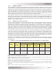
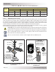

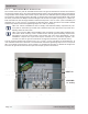
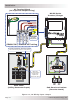
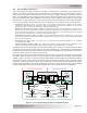
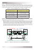
Table Of Contents
- 1.0 Introduction
- 2.0 Installation
- 3.0 Operation
- 4.0 Maintenance and Troubleshooting
- Appendix A – Specifi cations and Optional Equipment
- Appendix B - Battery Information
- Appendix C – Power Consumption and Output Waveforms
- Appendix D – Inverter/Charger Terminology
- Appendix E – Warranty and Service Information

Page 18
© 2013 Magnum Energy, Inc.
I nst alla t ion
2 .5 AC W ir ing
This section provides information on how to make the AC connections to the inverter using the
correct AC wire size and corresponding overcurrent protection.
2 .5 .1 Pre- AC W ir ing Re quir e m e nt s
CAUTI ON : Before installing any AC wiring, review the safety information at the
beginning of this manual and the following to ensure a safe and long-lived system:
• Always use properly rated circuit breakers. If using an electrical sub-panel, circuit
breakers can be moved from the main electrical panel to the sub-panel only if the
breakers are also listed to be installed in the sub-panel.
• AC wiring must be no less than 5.3 mm
2
(#10 AWG) gauge copper wire and be
approved for the application (i.e., residential, RV, or marine wiring).
• DO NOT connect the inverter’s output to an AC power source. This could cause
severe damage to the inverter and is not covered under warranty.
• The AC wire sizes recommended in this manual are based on the ampacities for
copper wire rated with 75ºC (167ºF) insulation at an ambient temperature of 30ºC
(86ºF).
W ARN I NG: To reduce the risk of fi re, do not connect this inverter to an AC load center
(circuit breaker panel) having multi-wire branch circuits connected.
2 .5 .2 AC W ir e Size a nd Ove r current Pr otect ion
The AC input and output wiring must be sized per the local electrical safety code requirements
to ensure the wire’s ability to safely handle the inverter’s maximum load current. The AC wiring
must be protected from short circuits and overloads by an overcurrent protection device and have
a means to disconnect the AC circuits. AC overcurrent protection is not included in the inverter
and must be provided as part of the inverter installation. The AC overcurrent protection device
must be a circuit breaker or a fuse/disconnect and be properly sized and branch circuit rated for
the wire it is protecting and the appliances being powered.
I nfo: When wiring the AC input and output circuits, we highly recommend a full
system Inverter Bypass Switch. This simple item provides a convenient way to isolate
the inverter for battery maintenance, and it could save you hours of downtime—if you
ever need to service your inverter—by enabling you to continue to power your AC loads
without any re-wiring. Because we think it is an essential part of an inverter system,
every Magnum panel (MMP-E/MP-E Series) is equipped with an inverter bypass switch.
When in Standby mode, the full AC continuous pass-thru capacity of the MS-PE Series inverter/
charger is 30 amps. For a 30-amp continuous pass-thru capability, the AC HOT IN input to the
inverter requires a 30-amp continuous duty rated breaker¹ , which corresponds to a minimum cable
size of 5.3 mm² (#10 AWG² ) in conduit. If you are using other circuit breakers/wire sizes, refer
to the appropriate local electrical codes and standards for proper sizing requirements.
CAUTI ON : The inverter’s internal AC transfer relay contacts are rated for 30 amps,
the pass-thru current must be no greater than 30 amps or damage to this relay may
occur.
N ot e ¹ – The breaker m ust be de- rat ed by 80% if not rated for continuous dut y. St andard safet y
pract ices require that circuits are not to be operat ed cont inuously at m ore than 80% of rat ing
unless listed wit h a 100% cont inuous rat ing.
N ot e ² – Copper wire rated with 75° C insulat ion at an am bient tem perat ure of 30° C (86° F).