
Owners Manual
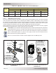

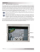
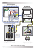
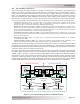
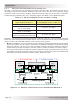
Table Of Contents
- 1.0 Introduction
- 2.0 Installation
- 3.0 Operation
- 4.0 Maintenance and Troubleshooting
- Appendix A – Specifi cations and Optional Equipment
- Appendix B - Battery Information
- Appendix C – Power Consumption and Output Waveforms
- Appendix D – Inverter/Charger Terminology
- Appendix E – Warranty and Service Information

© 2013 Magnum Energy, Inc.Page 19
I nst alla t ion
2 .5 .3 AC Term inal Block Connect ions
The inverter has a four-pole AC terminal block and one AC ground terminal to connect the inverter’s
AC input and output wiring. This terminal block allows either a service/distribution panel (main panel)
or a generator to be wired to the inverter’s input, and then to a dedicated panel (sub-panel) between
the inverter’s output wiring and the AC loads. To access and view the AC terminal block and ground
terminal, remove the two Phillips screws holding the AC access cover plate (see Figure 1-3, Item 15).
Each connection on the AC terminal block is rated to accept one 2.1 to 13.3 mm
2
(#14 to #6 AWG) CU
stranded wire, or two 3.3 mm
2
(#12 AWG) CU stranded wires. Each connection uses a M3.5 slotted
head screw, and the maximum tightening torque is 1.8 N-m (16 lbf-in).
I nfo: For marine installations and to comply with standard safety requirements, the
four-pole AC terminal is provided with a stainless steel wire protector to prevent wire
damage from the set-screw.
I nfo: The inverter’s NEUT IN and NEUT OUT terminals are electrically isolated from
each other while inverting. This is related to the neutral-ground bonding requirement
and helps to prevent ground-loops (see Section 2.6.5 for more information). If the
installation requires the input and output neutrals to be connected together, the
inverter’s neutral-to-ground connection must be disconnected (see Section 2.6.6).
The AC ground terminal can accept one 2.1 to 13.3 mm
2
(#14 to #6 AWG) CU stranded wire. It
uses a slotted head screw and has a recommended maximum tightening torque of 5.1 N-m(45 in
lbf). For multiple ground wires, use a pressure or mechanical connector to attach the single wire
from the AC ground terminal to the input and output ground connections.
HOT OUT
N EUT OUT
HOT I N
N EUT I N
AC
GROUND
( I n & Out )
Figure 2 - 8 , AC Te r m inal Block