
Installation Manual


© 2010 Magnum Energy, IncPage 19
Installation
2.5 AC Wiring
This section provides information on how to make the AC connections to the inverter using the
correct AC wire size and the corresponding overcurrent protection.
2.5.1 Pre-AC Wiring Requirements
CAUTION: Before installing any AC wiring, review the safety information and cautionary
markings at the beginning of this manual and the directions below to ensure a safe and
long-lived system:
Always use properly rated circuit-breakers. If using an electrical sub-panel, circuit
breakers can only be moved from the main electrical panel to the sub-panel if the
breakers are also listed to be installed in the sub-panel.
AC wiring must be no less than #12 AWG (3.3 mm
2
) gauge copper wire and be
approved for the application (i.e., house or cabin wiring).
DO NOT connect the inverter’s output to an AC power source. This could cause
severe damage to the inverter and is not covered under warranty.
•
•
•
WARNING: To reduce the risk of fi re, do not connect this inverter to an AC load center
(circuit breaker panel) having multi-wire branch circuits connected.
2.5.2 AC Wire Size and Overcurrent Protection
The AC input and output wiring must be sized per the local electrical safety code requirements to
ensure the wire’s ability to safely handle the inverter’s maximum load current. After determining
the proper AC wire sizes, they are required to be protected from short circuits and overloads by
an overcurrent protection device, and have a means to disconnect the AC circuits.
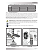
The RD Series allows the AC input and output wiring to be permanently wired. The inverter’s input
is wired to the service/distribution panel (main panel). The inverter’s output is then wired to a
dedicated panel (sub-panel). The inverter uses the circuit breakers provided in the panels as the
overcurrent protection and the AC disconnect device.
AC overcurrent protection isn’t included in the inverter and must be provided as part of the inverter
installation. The AC overcurrent protection device must be a circuit breaker or a fuse/disconnect,
be properly sized, and branch circuit rated for the wire it’s protecting and the appliances being
powered.
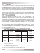
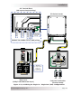
When in Standby Mode, the full AC continuous pass-thru capacity of the RD Series inverter/charger
is 30 amps for each AC leg (AC HOT1 and AC HOT2). However, the AC HOT1 and AC HOT2 may be
combined to obtain a 60 amps pass-thru capability (see Figure 2-12 for the SISO-60A confi guration).
For a 30 amp continuous pass-thru capability, each AC HOT IN input to the inverter requires a
30 amp continuous duty rated breaker
1
, which corresponds to a minimum cable size of #10 AWG
(5.3 mm
2
). When tying the AC HOT1 and HOT2 together for a 60 amp continuous pass-thru
capability, the AC input to the inverter requires a 60 amp continuous duty rated breaker, which
corresponds to a minimum cable size of #6 AWG. If you are using other circuit breakers/wire sizes,
refer to the appropriate electrical codes for proper sizing requirements.
CAUTION: The inverter’s internal AC transfer relay contacts are rated for 30 amps
per leg, the pass-thru current must be no greater than 30 amps per leg or damage to
this relay may occur.
Note 1 - The breaker must be de-rated by 80% if not rated for continuous duty. The NEC requires that circuits are not
to be operated continuously at more than 80% of rating unless listed with a 100% continuous rating.